
Cooling apparatus for water-cooled engine and method of controlling cooling apparatus for water-cooled engine

a technology of water-cooled engines and cooling apparatuses, which is applied in the direction of machines/engines, process and machine control, instruments, etc., can solve the problems of affecting so as to improve the startability of the engine

Inactive Publication Date: 2013-12-31
TOYOTA JIDOSHA KK
View PDF16 Cites 3 Cited by
  • Summary
  • Abstract
  • Description
  • Claims
  • Application Information

AI Technical Summary

Benefits of technology

[0009]The invention provides a cooling apparatus for a water-cooled engine, and a method of controlling a cooling apparatus for a water-cooled engine, which effectively improve startability of the engine when the engine is restarted immediately after the engine has been operated under a high load.
[0011]Thus, according to the first aspect of the invention, the cooling apparatus for a water-cooled engine includes a determination portion that determines whether the engine is operated under a high load; and a setting portion. If the determination portion determines that the engine is operated under a high load, the setting portion sets an operation rate of the radiator fan at a time point at which the determination portion determines that the engine is operated under a high load, to a value higher than a normal operation rate at the same coolant temperature as a coolant temperature at the time point. In this case, when the engine is operated under a high load, even if the coolant temperature is low, the radiator fan is operated at a high operation rate. Thus, when there is a possibility that the engine will be restarted in a high temperature condition after the engine is operated under a high load, it is possible to decrease in advance the temperatures of oil and coolant for the engine during the operation of the engine. Accordingly, with the above-described configuration, it is possible to effectively improve the startability of the engine when the engine is restarted immediately after the engine has been operated under a high load.
[0012]It is conceivable to operate the radiator fan after the engine is stopped after the engine has been operated under a high load. In this case as well, it may be possible to decrease in advance the temperatures of oil and coolant before the start of the engine, and therefore, it may be possible to improve the restartability. However, when the water-cooled engine is in a stopped state, operations of an alternator and a generator are also stopped. If the radiator fan is operated in this situation, there is a concern that the engine cannot be restarted due to a decrease in a power-feeding ability, which is caused by discharge of a battery. In contrast, in the above-described configuration, such a concern is eliminated, because the radiator fan is operated at a high operation rate during the operation of the engine.
[0014]With this configuration, when the engine is operated under a high load, the threshold value of the coolant temperature is set to a value lower than the normal threshold value. As a result, when the engine is operated under a high load, the operation of the radiator fan is started at a low coolant temperature. Thus, when there is a possibility that the engine will be restarted in a high temperature condition after the engine is operated under a high load, it is possible to decrease in advance the temperatures of oil and coolant for the engine during the operation of the engine. Accordingly, with the above-described configuration, it is possible to effectively improve the startability of the engine when the engine is restarted immediately after the engine has been operated under a high load.
[0016]With this configuration, when the engine is operated under a high load, the target cooling temperature of the coolant is set to a value lower than the normal target cooling temperature. That is, in this case, the radiator fan is operated to cool the coolant for the engine until the coolant temperature reaches the target cooling temperature lower than the normal target cooling temperature. Thus, when there is a possibility that the engine will be restarted in a high temperature condition after the engine is operated under a high load, it is possible to decrease in advance the temperatures of oil and coolant for the engine during the operation of the engine. Accordingly, with the above-described configuration, it is possible to effectively improve the startability of the engine when the engine is restarted immediately after the engine has been operated under a high load.
[0019]With this configuration, when the engine is operated under a high load, the threshold value of the coolant temperature is set to a value lower than a normal threshold value. As a result, when the engine is operated under a high load, the operation of the radiator fan is started at a low coolant temperature. Thus, when there is a possibility that the engine will be restarted in a high temperature condition after the engine is operated under a high load, it is possible to decrease in advance the temperatures of oil and coolant for the engine during the operation of the engine. Accordingly, with the above-described configuration, it is possible to effectively improve the startability of the engine when the engine is restarted immediately after the engine has been operated under a high load.

Problems solved by technology

When employing the cooling apparatus for a water-cooled engine, which includes the radiator and the radiator fan, if the engine is stopped immediately after the engine has been operated under a high load, a temperature around the engine may sharply increase due to the stop of the radiator fan.
If the engine is restarted in this situation, fuel vapor may be generated, and therefore, the startability may deteriorate.
However, when the water-cooled engine is in a stopped state, operations of an alternator and a generator are also stopped.
If the radiator fan is operated in this situation, there is a concern that the engine cannot be restarted due to a decrease in a power-feeding ability, which is caused by discharge of a battery.

Method used


Image

  • Cooling apparatus for water-cooled engine and method of controlling cooling apparatus for water-cooled engine
  • Cooling apparatus for water-cooled engine and method of controlling cooling apparatus for water-cooled engine
  • Cooling apparatus for water-cooled engine and method of controlling cooling apparatus for water-cooled engine

Examples


Embodiment Construction

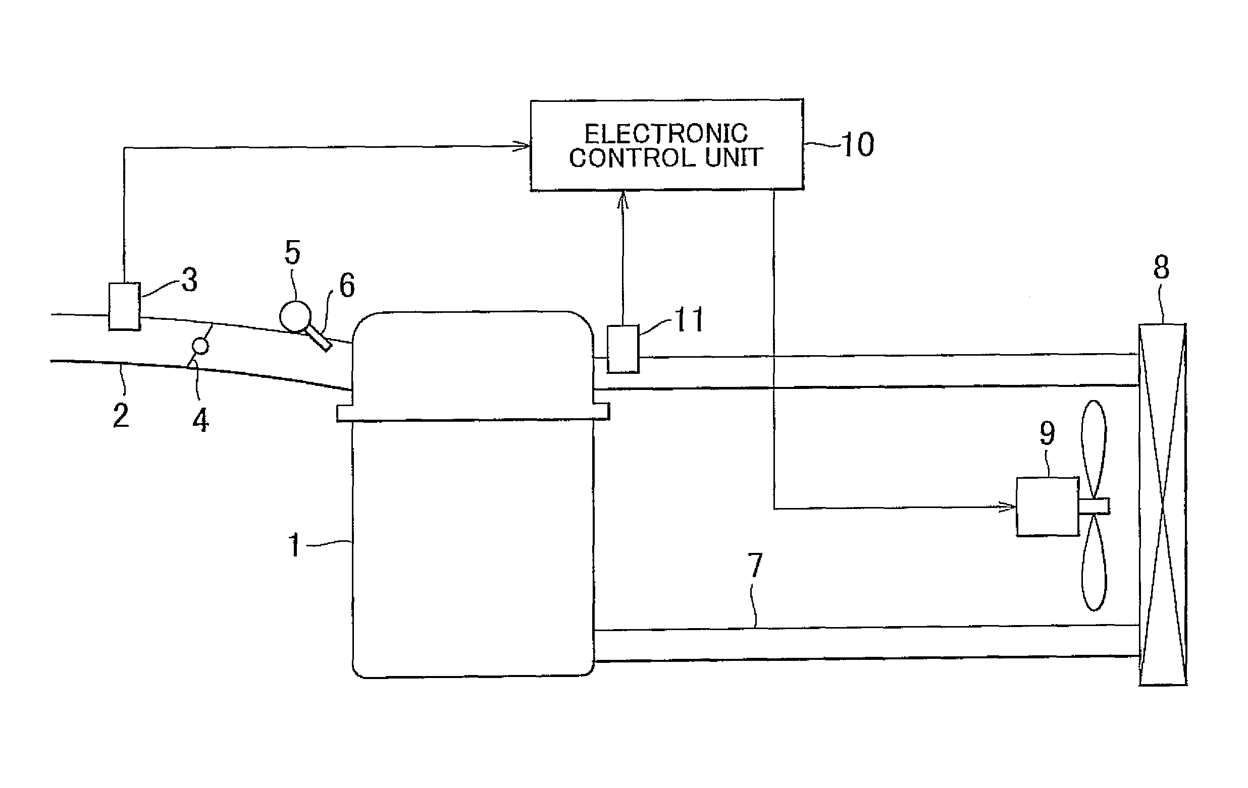
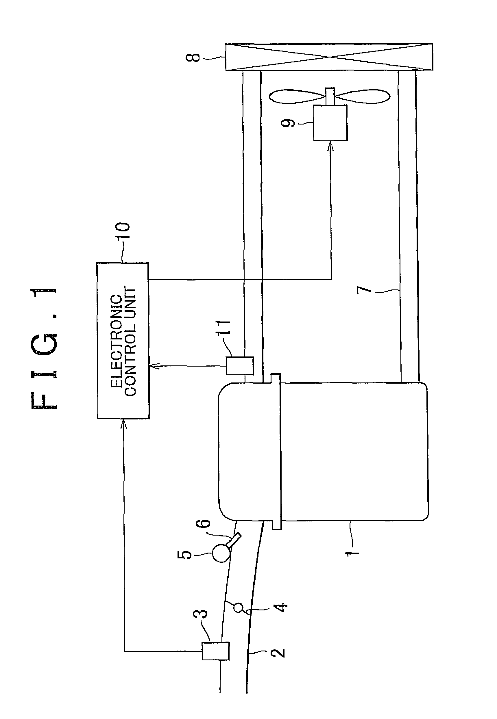
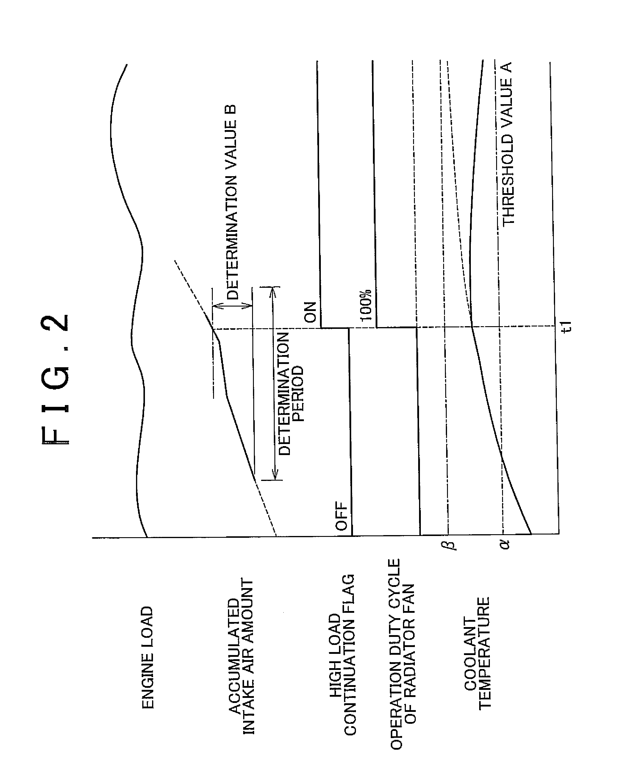
[0026]Hereinafter, a cooling apparatus for a water-cooled engine according to an embodiment of the invention will be described in detail with reference to FIG. 1 to FIG. 3. FIG. 1 shows the configuration of the entire cooling apparatus for a water-cooled engine according to the embodiment. As shown in FIG. 1, in an intake passage 2 of a water-cooled engine 1 to which the cooling apparatus according to the embodiment is applied, an airflow meter 3, a throttle valve 4, and an injector 6 are provided. The airflow meter 3 detects an intake air amount. The throttle valve 4 adjusts the intake air amount. The injector 6 injects fuel accumulated in a delivery pipe 5, into intake air. The water-cooled engine 1 is connected to a coolant circulation passage 7. Coolant, which has passed through a water jacket formed in the water-cooled engine 1, is circulated through the coolant circulation passage 7. The coolant circulation passage 7 is provided with a radiator 8 in which the coolant is cooled...


PUM


Abstract

A cooling apparatus for a water-cooled engine includes a radiator that cools coolant that has been circulated in the engine; a radiator fan that delivers air to the radiator; a determination portion that determines whether the engine is operated under a high load; and a setting portion. If the determination portion determines that the engine is operated under a high load, the setting portion sets an operation rate of the radiator fan at a time point at which the determination portion determines that the engine is operated under a high load, to a value higher than a normal operation rate at the same coolant temperature as a coolant temperature at the time point.

Description

CROSS-REFERENCE TO RELATED APPLICATION[0001]This application claims priority to Japanese Patent Application No. 2010-057691 filed on Mar. 15, 2010, which is incorporated herein by reference in its entirety including the specification, drawings and abstract.BACKGROUND OF THE INVENTION[0002]1. Field of the Invention[0003]The invention relates to a cooling apparatus for a water-cooled engine, and a method of controlling a cooling apparatus for a water-cooled engine. More particularly, the invention relates to improvement in a control structure of a cooling apparatus, for improving restartability of an engine when the engine is restarted immediately after the engine has been operated under a high load.[0004]2. Description of the Related Art[0005]A water-cooled engine is cooled by circulating coolant in a water jacket formed in a cylinder head and a cylinder block, and delivering air to a radiator to cool the coolant whose temperature has been increased by heat received from the engine. ...

Claims


Application Information

Patent Timeline
Patent Type & Authority Patents(United States)
IPC IPC(8): F01P7/02
CPCF01P7/048F01P2025/62
Inventor SUZUKI, TATSUAKI
Owner TOYOTA JIDOSHA KK
Learn More