Nozzle body for a liquid droplet spray device
a spray device and liquid droplet technology, applied in the direction of burners, disinfection, combustion types, etc., can solve the problems of large droplets that take longer to evaporate before falling back, droplets falling back down before being evaporated, etc., to achieve the effect of minimizing the fall back, and reducing the fall back
- Summary
- Abstract
- Description
- Claims
- Application Information
AI Technical Summary
Benefits of technology
Problems solved by technology
Method used
Image
Examples
first embodiment
[0022
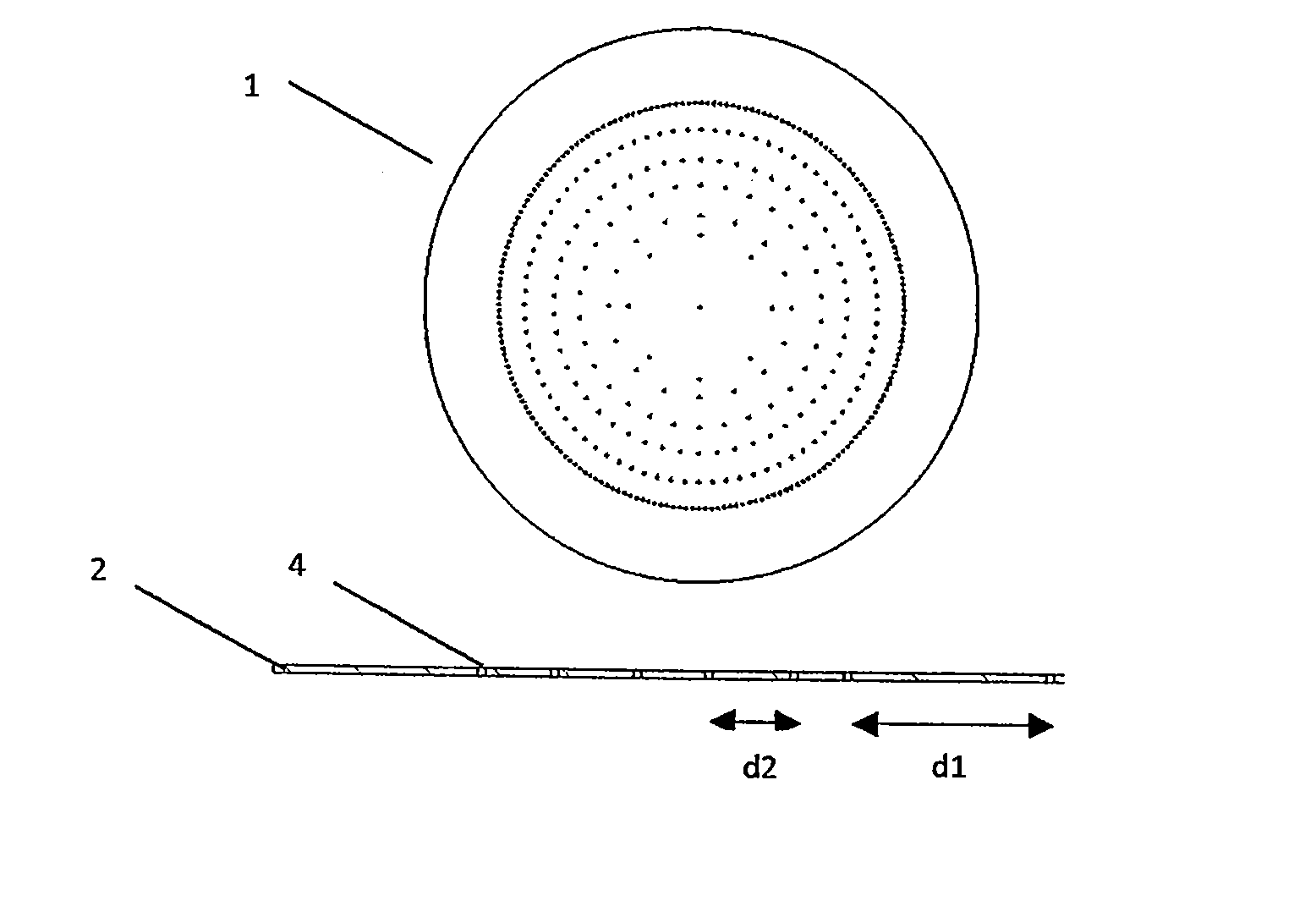
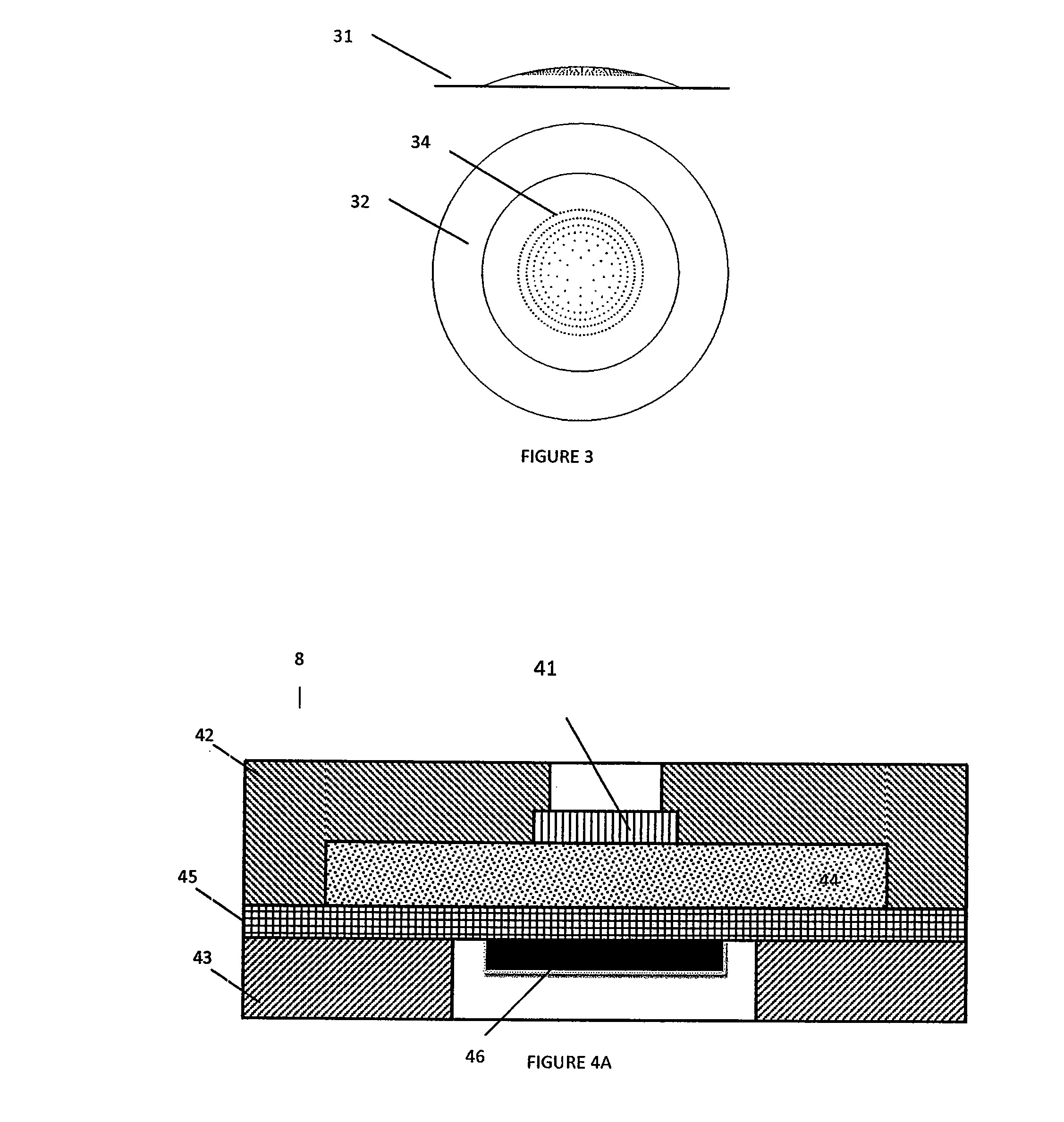
[0023]FIG. 1 shows an example of a nozzle body suitable for a liquid droplet spray device in a first embodiment according to the present invention. Nozzle body 1 is arranged to receive a liquid substance from the liquid droplet spray device in a known manner and consists of a substrate 2 provided with traversing output nozzles 4. Substrate 2 may be made of silicon or plastics or the like. The main requirement for the substrate 2 is that the material used can be pierced to obtain traversing output nozzles with straight sidewalls. A plurality of output nozzles 4 is provided as fluid passages to allow liquid to be expelled from the spray device in a manner known in the art. For example, in a manner known as such (see also FIG. 4A), a liquid chamber 44 may be provided adjacent to the nozzle body 41, and the liquid may be put into vibration by ultrasound generating means 46, such as a piezoelectric actuator, such that the ultrasound acts on the liquid forcing it through the output n...
second embodiment
[0027
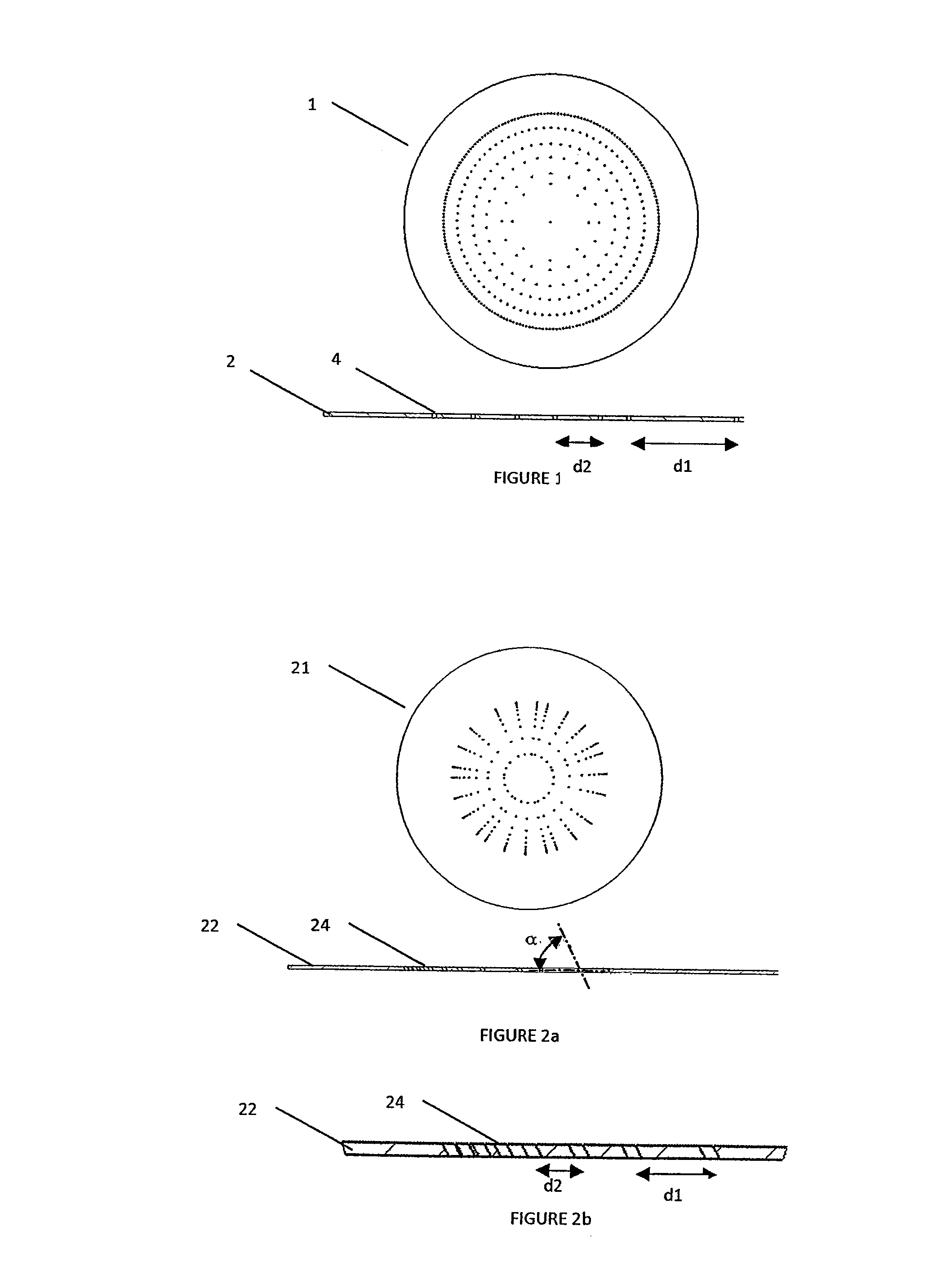
[0028]FIG. 2 shows an example of a nozzle body suitable for a liquid droplet spray device in a second embodiment according to the present invention. Nozzle body 21 of this second embodiment is similar to the nozzle body 1 of the first embodiment, except for the arrangement of the output nozzles. Similar parts and arrangements will not be described here in detail. As shown in FIG. 2a, nozzle body 21 differs from nozzle body 1 in that the output nozzles 24 located away from the centre, and towards the edges of the substrate 22, are inclined and are arranged at an angle α, where 024 closer to the edge of the substrate 22 may be all arranged at the same angle α or may have varying angles α, where this angle α may decrease, for instance from less than 90° towards 0° when going from the centre of substrate 12 towards its edges.
[0029]Thanks to this inclination, the resulting expelled cloud has a lower density in its middle as compared to a conventional spray device with a regular arra...
third embodiment
[0031
[0032]FIG. 3 shows an example of a nozzle body suitable for a liquid droplet spray device in a third embodiment according to the present invention. Nozzle body 31 of this third embodiment is similar to the nozzle body of the first embodiment, except for the output nozzles and the geometry of the nozzle body. Similar parts and arrangements will not be described here in detail. Nozzle body 31 differs from nozzle body 1 in that the output nozzles 34 have varying diameters, smaller when arranged near the centre of the substrate 32 and larger when arranged towards the edges of substrate 32. Thus, the traversing nozzles 34 may have different diameters resulting in different nozzle sizes and thus in different droplet sizes being expelled.
[0033]Of course, it is also possible to arrange the nozzles such that a desired spray is obtained, for example by having a mix of different sized nozzles in the centre and towards the edges. As shown in FIG. 3, the substrate has a domed central region...
PUM
 Abstract
Description
Claims
Application Information
 - R&D
- Intellectual Property
- Life Sciences
- Materials
- Tech Scout
- Unparalleled Data Quality
- Higher Quality Content
- 60% Fewer Hallucinations
Browse by: Latest US Patents, China's latest patents, Technical Efficacy Thesaurus, Application Domain, Technology Topic, Popular Technical Reports.
© 2025 PatSnap. All rights reserved.Legal|Privacy policy|Modern Slavery Act Transparency Statement|Sitemap|About US| Contact US: help@patsnap.com


