Syringe for articular cavity
A syringe and joint cavity technology, applied in the field of medical devices, can solve the problems of inability to effectively extract fluid in the joint cavity, articular cartilage, blood vessel injury, low universality of the syringe, etc., and achieve simple structure, improved safety, and reliability sex high effect
- Summary
- Abstract
- Description
- Claims
- Application Information
AI Technical Summary
Problems solved by technology
Method used
Image
Examples
Embodiment 1
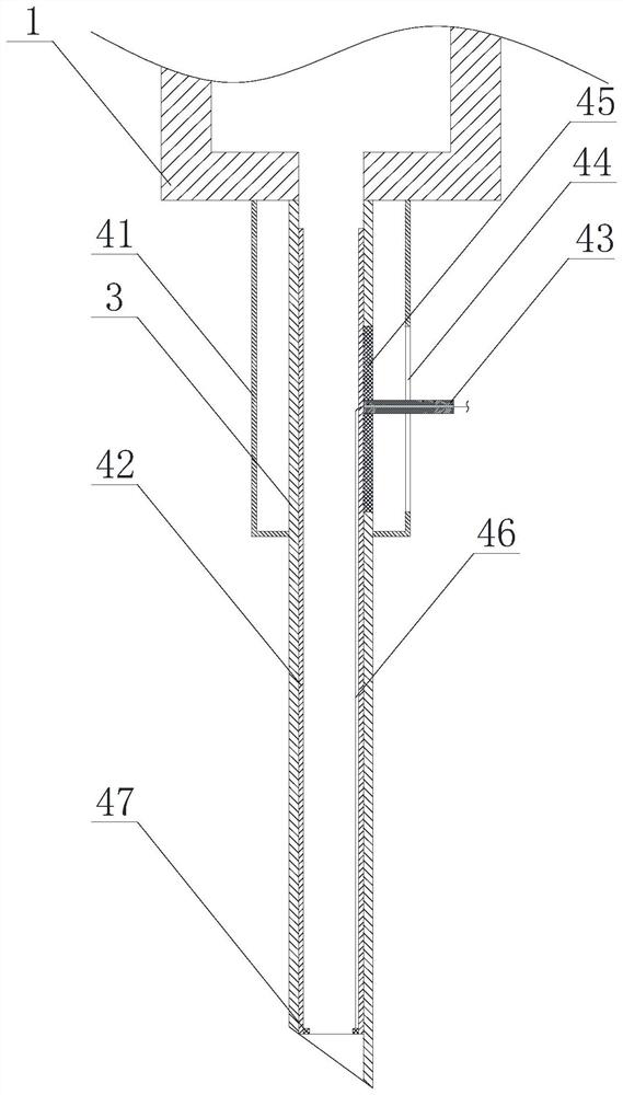
[0051] Such as Figure 1 to Figure 5 A syringe for the joint cavity is shown, comprising a syringe 1 and an outer needle 3 connected to the syringe 1, an inner needle 42 that can slide relative to the outer needle 3 is arranged inside the outer needle 3, the The inner needle 42 is made of flexible material;
[0052] The syringe also includes a control mechanism, the control mechanism is used to control the syringe to switch to the needle-out state or the needle-retract state, and in the needle-out state, the bottom end of the inner needle 42 extends to the outside of the outer needle 3 , in the narrowing state, the bottom end of the inner needle 42 is retracted to the inside of the outer needle 3 .
[0053] In some embodiments, such as figure 1 As shown, the outer needle head 3 is provided with a scale line 31 .
[0054] In one or more embodiments, the inner needle 42 is made of medical silicone rubber.
[0055] In one or more embodiments, preferably, the outer wall of the...
Embodiment 2
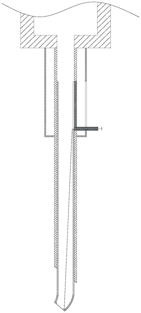
[0059] On the basis of Example 1, such as figure 2 and image 3 As shown, the control mechanism includes a control cylinder 41 sleeved on the outside of the outer needle head 3, and a chute 44 is opened on the control cylinder 41, and a control rod 43 is slidably arranged in the chute 44. The needle 3 is provided with an opening, the control rod 43 moves through the opening and is connected to the outer wall of the inner needle 42, and the control rod 43 is used to drive the inner needle 42 to move vertically.
[0060] In some embodiments, a traction rope 46 is connected to the bottom end of the inner needle 42 , and the traction rope 46 passes through the control cylinder 41 . During the descent process, when articular cartilage and blood vessels appear on the moving path of the inner needle, although the inner needle can use its own deformation to reduce the damage to the surrounding tissues, due to the small and complex volume of the joint cavity, there is still a certain...
Embodiment 3
[0066] On the basis of Example 1, such as Figure 4 and Figure 5 As shown, the control mechanism includes a control cylinder 41 sheathed on the outside of the outer needle 3, a rotating member 51 is provided on the control cylinder 41, and a gear is provided on one end of the rotating member 51 located in the control cylinder 41. 52, the outer needle head 3 is provided with an opening, and a push rod 55 connected to the outer wall of the inner needle head 42 is slidably arranged in the opening, and a transmission rod 53 is connected to the push rod 55, and a transmission rod 53 is provided on the transmission rod 53 The rack 54 is engaged with the gear 52 .
[0067] When controlling, by rotating the rotating part, the gear can be driven to rotate clockwise or counterclockwise. Through the meshing of the gear and the rack, the transmission rod is driven to move up or down in the vertical direction, and then the push rod and the inner needle head are driven to move vertically....
PUM
 Abstract
Description
Claims
Application Information
 - R&D
- Intellectual Property
- Life Sciences
- Materials
- Tech Scout
- Unparalleled Data Quality
- Higher Quality Content
- 60% Fewer Hallucinations
Browse by: Latest US Patents, China's latest patents, Technical Efficacy Thesaurus, Application Domain, Technology Topic, Popular Technical Reports.
© 2025 PatSnap. All rights reserved.Legal|Privacy policy|Modern Slavery Act Transparency Statement|Sitemap|About US| Contact US: help@patsnap.com


