Hoist using friction wheel

a technology of friction wheel and hoist, which is applied in the direction of hoisting equipment, load-engaging elements, transportation and packaging, etc., can solve the problems of increasing the total size of the hoist, increasing the power consumption, and the conventional hoist, so as to prevent damage to parts or wires, expand the lifting range of loads, and prevent damage to wires

Inactive Publication Date: 2013-12-31
KG INC
View PDF11 Cites 8 Cited by
  • Summary
  • Abstract
  • Description
  • Claims
  • Application Information

AI Technical Summary

Benefits of technology

[0025]As is apparent from the above description, in a hoist using a friction wheel according to the present invention, a wire repeatedly wound on upper and lower sheaves is guided to the top of a friction wheel after passing through an auxiliary sheave located at one side of the upper sheave to thereby be wound on the friction wheel. Thus, the wire at a winding side is directly connected from the top of the auxiliary sheave to the top of the friction wheel, rather than passing through a narrow vertical space between the friction wheel and the upper sheave, which prevents the wire at the winding side extending from the upper sheave to the friction wheel from coming into contact with other parts even in the event of horizontal movement of the upper or lower sheave and in turn, prevents damage to the parts or the wire. Further, considerably expanding a horizontal movement range of the upper or lower sheave can result in an expanded lifting range of a load with considerably enhanced lifting efficiency.
[0026]According to the present invention, a vertical movable guide roller is installed to a side plate near a horizontal movable guide roller so as to be horizontally reciprocated on a wire drum drive shaft to allow the wire at a drawing side to be gradually wound on the outer circumference of a wire drum. As the wire at the drawing side wound on the wire drum is gradually wound on the circumference of the wire drum by being moved from one side to the other side of the wire drum under the guidance of the vertical movable guide roller, the wire is stably wound on the wire drum without deviating from a winding orbit thereof.
[0027]According to the present invention, a single friction wheel is mounted on the friction wheel drive shaft, which results in a more simplified configuration than the previously described conventional hoist using a pair of friction wheels and a pinion and in turn, reduced product costs and more simplified assembly operation.
[0028]According to the present invention, a driven friction wheel is installed below the friction wheel so as to perform idle rotation. The driven friction wheel serves only to guide the wire and thus, is rotated at the same revolutions per minute as the friction wheel, which can prevent slippage between the friction wheel, the driven friction wheel and the wire.
[0029]According to the present invention, a wire drum drive shaft recess formed in the side plate is upwardly open such that both the ends of the wire drum drive shaft can be simply seated in the wire drum drive shaft recesses of the two side plates by first positioning both ends of the wire drum drive shaft above the wire drum drive shaft recesses and then lowering them into the wire drum drive shaft recesses. Thus, the wire drum can be assembled to or disassembled from the side plates of a main frame in a very simple manner, which results in a considerable reduction in the assembly and service times.
[0030]According to the present invention, the horizontal movable guide rollers are stably installed to a mounting bracket surrounding upper and lower sides and front and rear sides of the horizontal movable guide rollers, and to coupling shafts coupled to the mounting bracket and the horizontal movable guide rollers to allow the horizontal movable guide rollers to be supported by the mounting bracket. In addition, the horizontal and vertical movable guide rollers are installed to the movable roller mount, which is installed to the side plate so as to come into contact at three points with a single motor shaft and two guide shafts. Thus, as the movable roller mount is stably reciprocated on the guide shafts while being supported at the aforementioned three points, the horizontal and vertical movable guide rollers installed to the movable roller mount are movable while being kept in a stably supported state, which assures that the wire at the drawing side be stably wound on the wire drum without deviating from a winding orbit thereof.

Problems solved by technology

Therefore, the conventional hoist has problems, such as the increase of the total size of the hoist according to the increase of the rising and falling distance of the load block, and the increase of power consumption.
As the wire at the winding side is connected from the lower sheave to the friction wheels through the narrow space, it is impossible to control a position of the lower sheave within a wide range.
For example, when the lower sheave is horizontally moved to hang the load to be lifted on the hook, the wire at the winding side may come into contact with the bottom of the friction wheels or the upper sheave, which disadvantageously results in damage to parts in contact with the wire at the winding side to which a great force is applied, or damage to the wire due to unnecessary contact.
In conclusion, positioning the wire at the drawing side, which extends from the lower sheave to the friction wheels, in the narrow space considerably limits a horizontal movement range of the lower sheave and consequently, limits a lifting range of the load, resulting in considerable deterioration in lifting efficiency.
In addition, in the hoist using the conventional friction wheel, the wire at the drawing side may be wound on the wire drum in an unstable state thereof.
This may prevent the wire from being sequentially wound on the circumference of the wire drum starting from one side to the other side of the wire drum and frequently causing the wire to deviate from a winding orbit thereof.
The conventional hoist using friction wheels also suffers from a complicated configuration of the friction wheels.
Thus, the configuration consisting of the two friction wheels and the pinion is somewhat complicated and production costs and assembly difficulty are increased accordingly.

Method used


Image

  • Hoist using friction wheel
  • Hoist using friction wheel
  • Hoist using friction wheel

Examples


Embodiment Construction

[0042]Reference will now be made in detail to characteristics and advantages of embodiments of the present invention, examples of which are illustrated in the accompanying drawings.

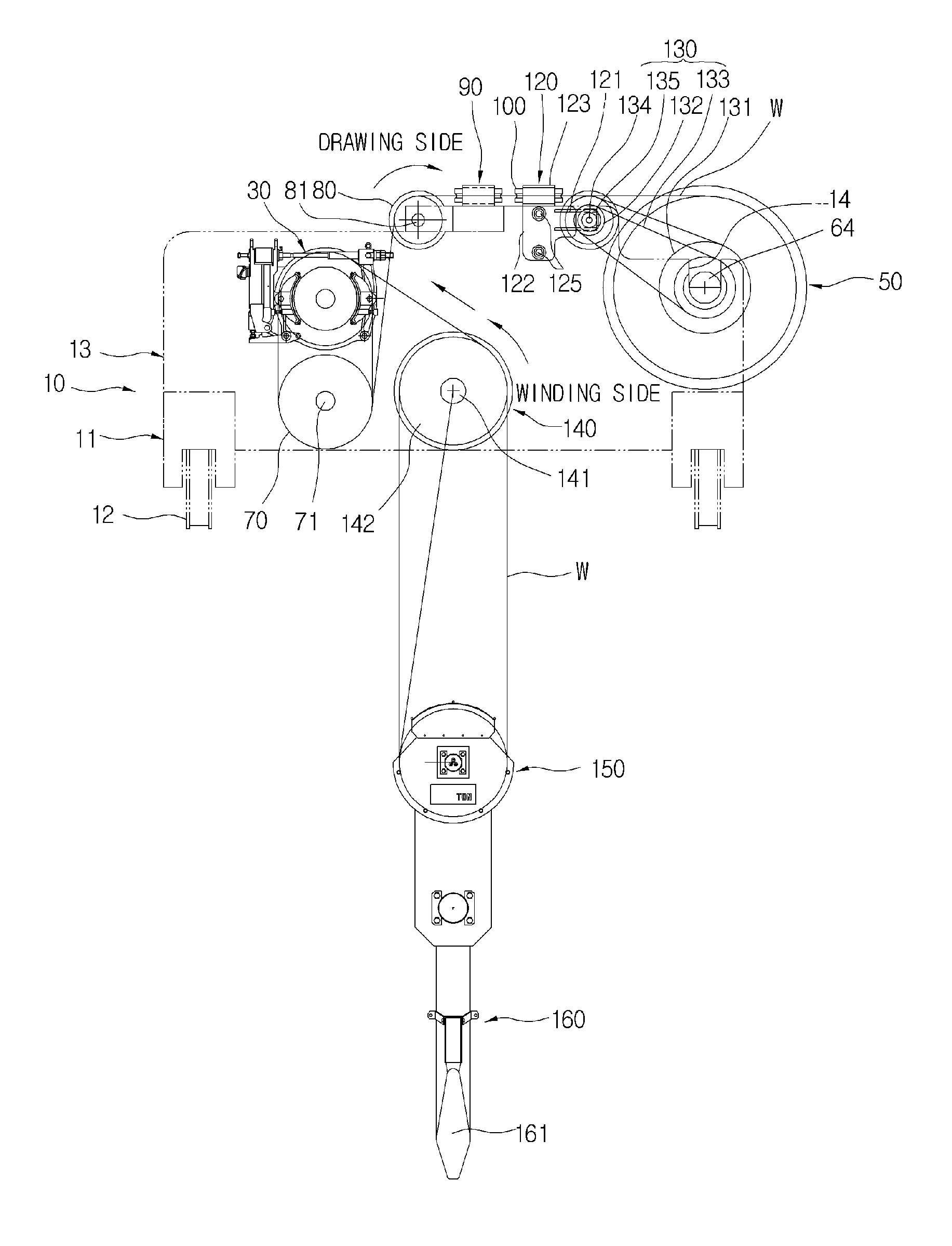
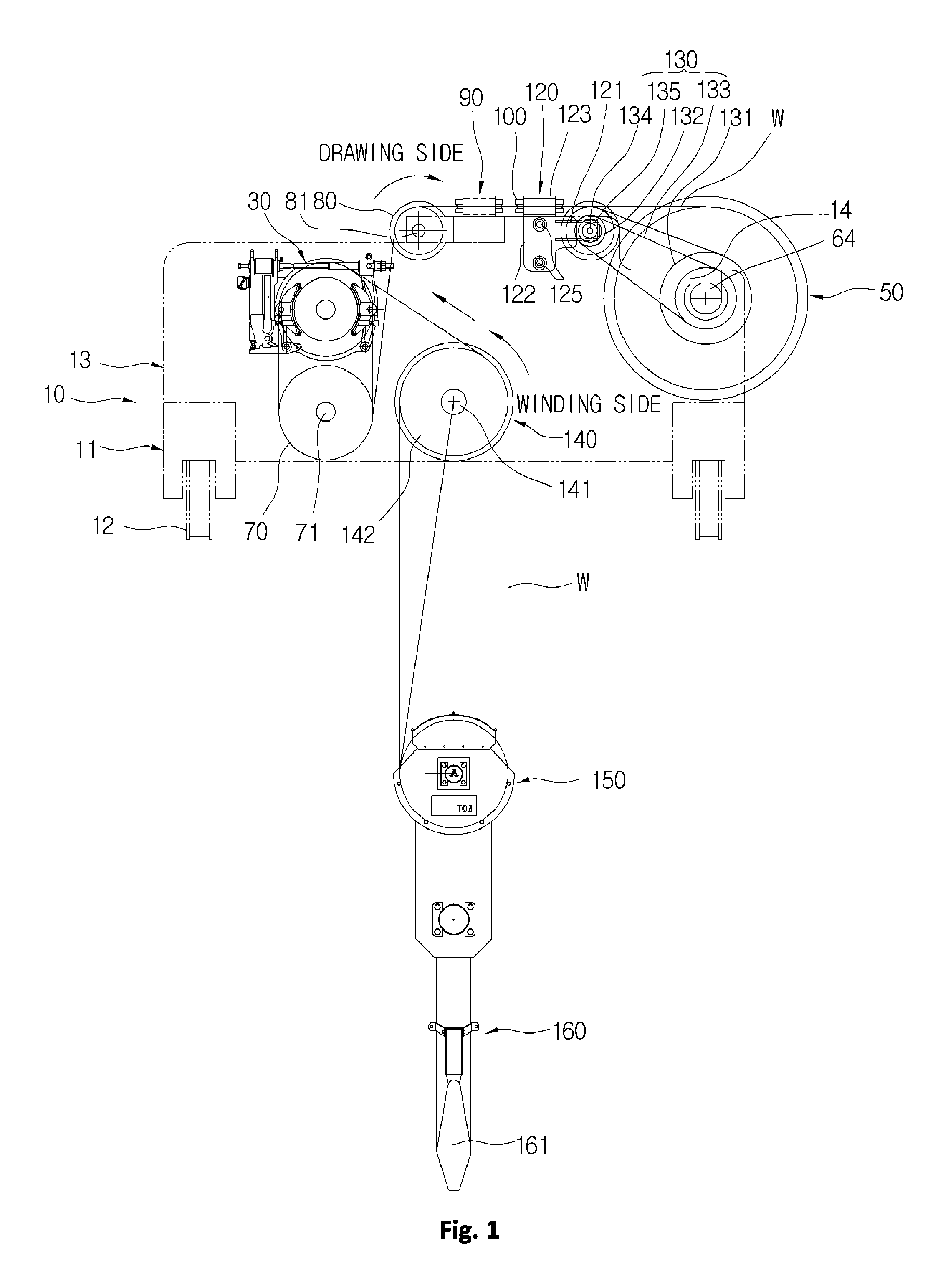
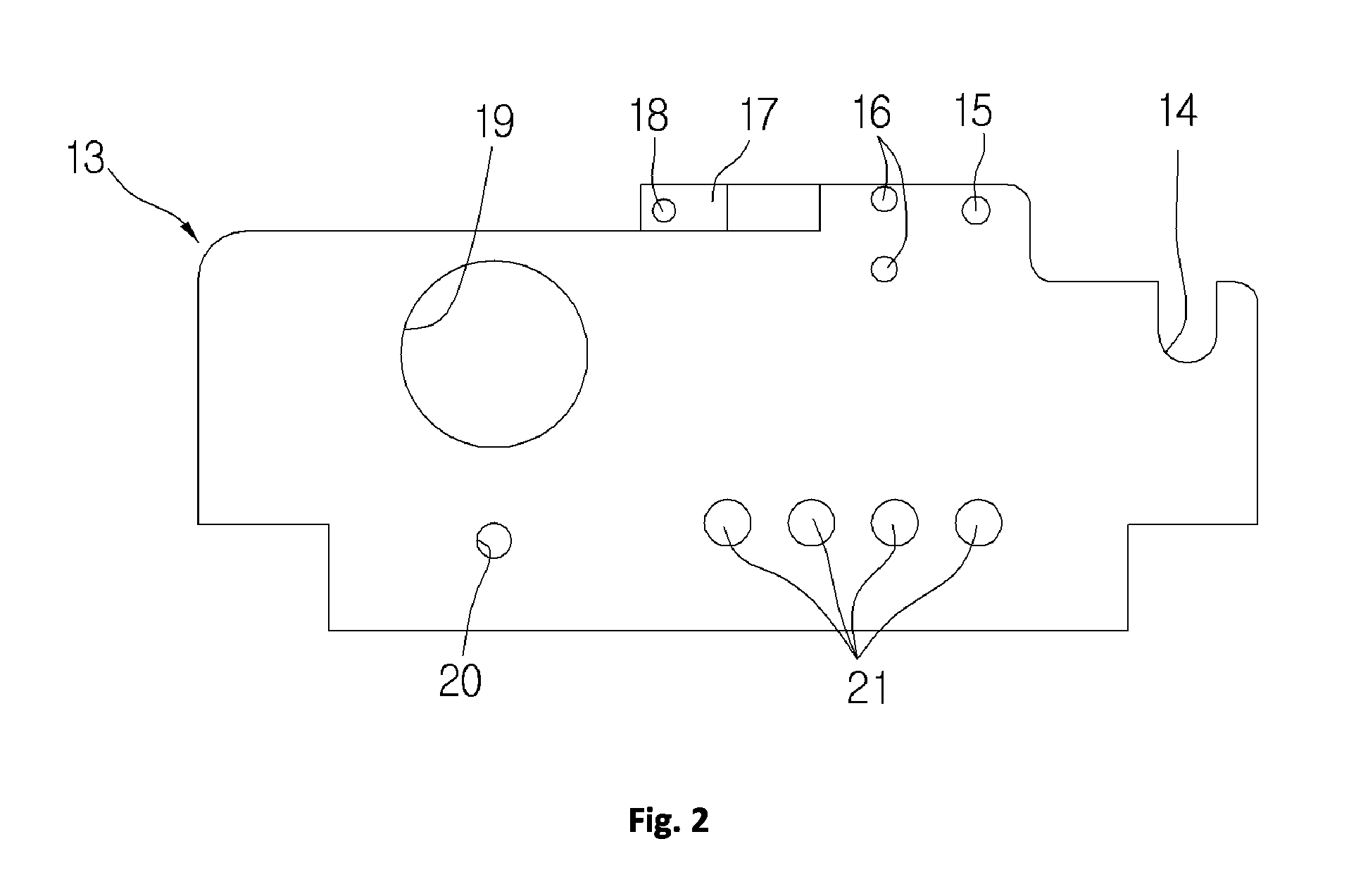
[0043]FIG. 1 is a schematic front view illustrating a hoist using a friction wheel in accordance with the present invention, FIG. 2 is a front view of a side plate included in the hoist, FIG. 3 is a schematic side view of FIG. 1, FIG. 4 is a schematic plan view of FIG. 1, FIG. 5 is a partial front view illustrating important parts of the present invention, FIG. 6 is a partial side view illustrating a coupling configuration of a horizontal movable guide roller, FIG. 7 is a partial plan view of FIG. 4, FIG. 8 is a schematic partial perspective view illustrating an installation configuration of a horizontal movable guide roller and a vertical movable guide roller, and FIG. 9 is a partial front view illustrating an auxiliary sheave.

[0044]The hoist using a friction wheel in accordance with the present inventio...


PUM


Abstract

Disclosed is a hoist using a friction wheel to maximize horizontal movement of a load to be lifted while preventing a wire from deviating from a winding orbit while being wound on a wire drum, the friction wheel having a simplified configuration and being designed to stably support horizontal and vertical movable guide rollers. The hoist includes a single friction wheel on which a wire at a winding side is wound, a wire drum on which the wire at a drawing side is wound, a driven friction wheel through which the wire is guided from the friction wheel to the wire drum, vertical and horizontal stationary guide rollers and vertical and horizontal movable rollers for guidance of the wire, a movable roller mount to horizontally reciprocate the horizontal and vertical movable guide rollers, and upper and lower sheaves to guide the wire to the friction wheel.

Description

TECHNICAL FIELD[0001]The present invention relates to a hoist using a friction wheel, and more particularly, to a hoist using a friction wheel, which can maximize a horizontal movement range of a load to be lifted and prevent a wire at a drawing side from deviating from a winding orbit while being wound on a wire drum, the friction wheel used in the hoist having a simplified configuration and being designed to stably support horizontal and vertical movable guide rollers.BACKGROUND ART[0002]In general, a hoist is used to convey goods in a warehouse and a railroad station and to disassemble and assemble machinery in a plant. The hoist is a kind of machinery, which serves to raise or lower a cargo using a wire and constitutes a group including, e.g., a motor, a reduction gear device and a wire drum, the hoist being provided with a hook at the tip of a wire thereof so as to lift the cargo.[0003]The above described hoist includes a main frame, on which a plurality of parts is installed, ...

Claims


Application Information

Patent Timeline
Patent Type & Authority Patents(United States)
IPC IPC(8): B66D1/36
CPCB66D1/20B66C1/36B66D1/36B66D1/12
Inventor CHO, DUCK-RAE
Owner KG INC
Why Eureka
Try Eureka