Hollow pot

a pot and lid technology, applied in the field of pots, can solve the problems of leakage of water that cannot be absorbed by the soil, difficult cleaning, and noise generation of leakag

Inactive Publication Date: 2014-01-07
TSAI CHIN TAI
View PDF19 Cites 7 Cited by
  • Summary
  • Abstract
  • Description
  • Claims
  • Application Information

AI Technical Summary

Benefits of technology

[0006]Furthermore, the liquid in the space of the pot moves upward via the path due to siphon effect so that the soil in the reception area absorbs the water. The pressure of inside the space is lower than the atmosphere so that the pressure is supplied into the space via the path to let the water in the space to move upward to automatically water the soil. Therefore, the soil of the pot is always supplied by small amount of water and the humidity of the soil is proper for the roots of the plant. The special arrangement allows the owners of the plant to travel for a period of days while the soil is supplied sufficient water.

Problems solved by technology

However, people in the modern world are busy and may not able to regularly water the plant and some people thought that the more water to the plant, the healthier the plant will be so that more than needed water is poured to the pot and the water that cannot be absorbed by the soil leaks from the hole in the bottom of the pot.
The water and the soil that leak from the hole of the pot directly drop to the floor and form dark spots which are difficult to clean up.
If the pot is located at a higher position, the leakage may generate noise.
In the daytime, the temperature in the pot increases so that the humidity and temperature are trapped in the soil so that the roots of the plant are easily decayed.
Besides, if the owner leaves for couple of days, the plant will be dead because no water is supplied.

Method used


Image

  • Hollow pot
  • Hollow pot
  • Hollow pot

Examples


Embodiment Construction

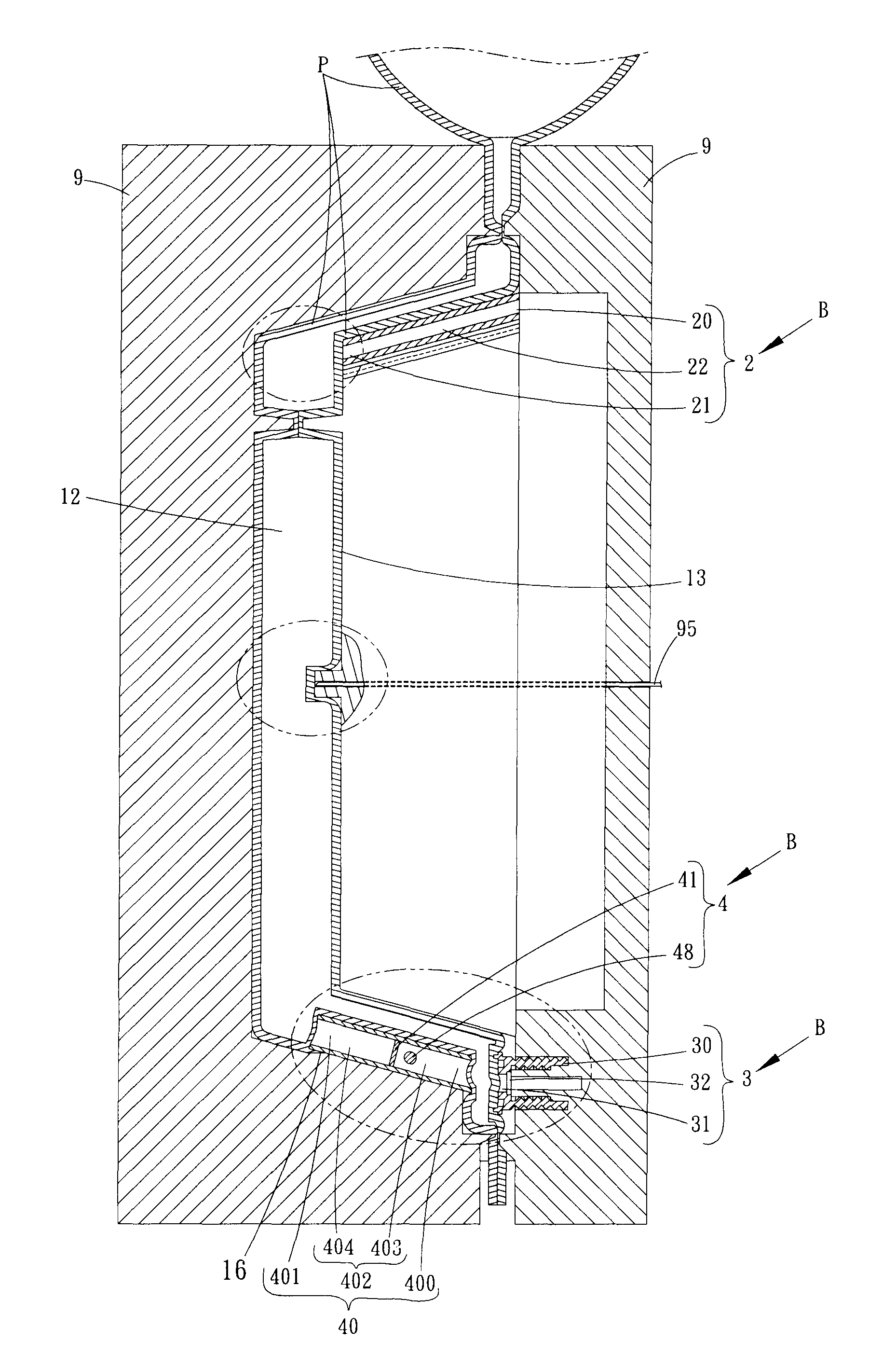
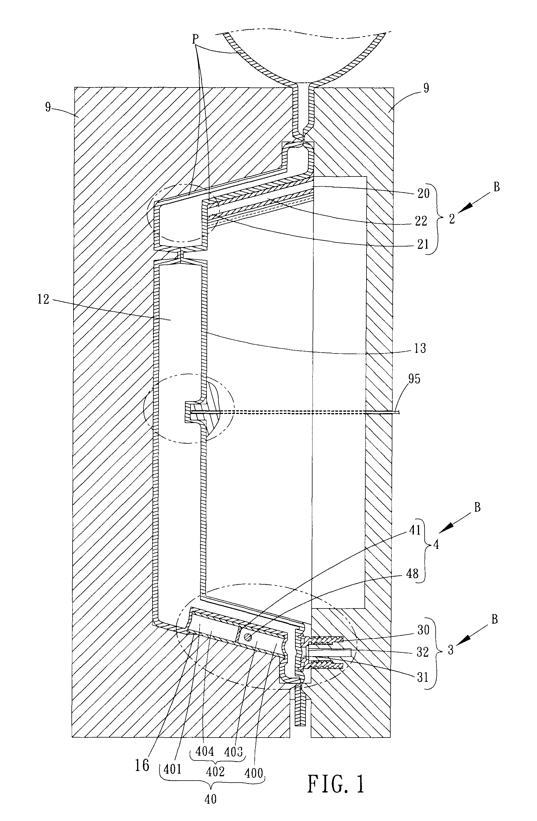
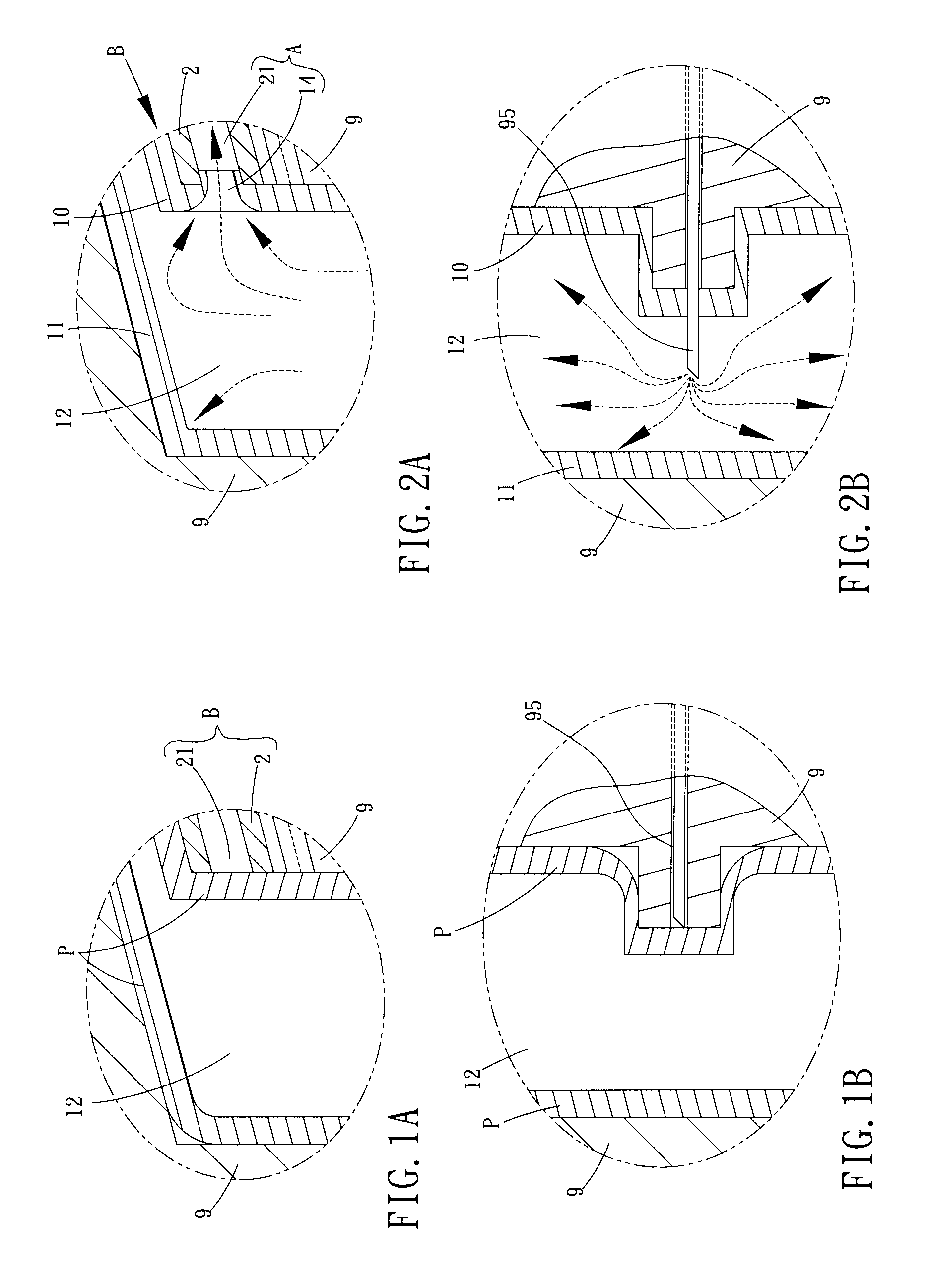
[0025]Referring to FIGS. 1 to 11, the hollow pot of the present invention comprises a pot unit 1 and a connection unit B.

[0026]The pot unit 1 has an inner layer 10 with a recessed reception area 13 defined therein, an outer layer 11 supporting the inner layer 10, and a space 12 located between the inner and outer layers 10, 11. A through hole 133 is located in communication between the reception area 13 and the space 12. A water introducing unit 3 is located in communication between the space 12 and outside of the pot unit 1. A seal unit 6 seals the water introducing unit 3, and a path A communicates between the space 12 and the outside of the pot unit 1. The reception area 13 of the inner layer 10 has a recessed area 131 and at least one through hole 133 is defined in the recessed area 131. The through hole 133 communicates with the space 12. The through hole 133 is integrally formed simultaneously with the formation of the pot unit 1, or the through hole 133 is formed by drilling ...


PUM

PropertyMeasurementUnit
transparentaaaaaaaaaa
temperatureaaaaaaaaaa
humidityaaaaaaaaaa

Abstract

A hollow pot includes a pot unit and a connection unit. The connection unit is a hollow unit and installed to inner surface of a mold set before pressurized air is introduced in the mold set and before the mold set is closed. A probe is inserted into the mold set and blows the plastic material in the mold set. The plastic material expands and contacts against the inner surface of the mold set and seals the connection holes of the connection unit. The plastic material is extended and broken to match upon the connection holes of the connection unit. The plastic material is solidified to form the pot unit. The pot unit is air-tightly connected to the connection unit, and the conjunction area of the connection unit communicates with the space in the pot unit.

Description

FIELD OF THE INVENTION[0001]The present invention relates to a pot, and more particularly, to a hollow pot with a space defined therein so as to store water in the space to provide the plant sufficient water.BACKGROUND OF THE INVENTION[0002]A conventional pot for plant generally is made by pottery clay, porcelain or plastic, and includes a single layer with the inside and the outside. A hole is defined in the bottom of the pot which has an open top so that soil is put in the pot via the open top. The plant is planted in the soil.[0003]However, people in the modern world are busy and may not able to regularly water the plant and some people thought that the more water to the plant, the healthier the plant will be so that more than needed water is poured to the pot and the water that cannot be absorbed by the soil leaks from the hole in the bottom of the pot. The water and the soil that leak from the hole of the pot directly drop to the floor and form dark spots which are difficult to...

Claims


Application Information

Patent Timeline
Patent Type & Authority Patents(United States)
IPC IPC(8): A01G27/02
CPCB29L2031/7136A01G27/02B29C2793/0018B29C2793/00B29C49/20A01G9/02B29C49/16
Inventor TSAI, CHIN-TAI
Owner TSAI CHIN TAI
Why Eureka
Try Eureka