
Single burner snow melter capable of a snow start operation

a single burner, snow melting technology, applied in lighting and heating apparatus, combustion process, drying, etc., can solve the problems of large and cumbersome apparatus, large amount of fuel lowering efficiency, and devices generally creating a substantial amount of noise, so as to achieve more efficient distribution of combustion gases

Active Publication Date: 2014-01-14
TRECAN COMBUSTION
View PDF31 Cites 1 Cited by
  • Summary
  • Abstract
  • Description
  • Claims
  • Application Information

AI Technical Summary

Benefits of technology

The present invention is about a snow melting apparatus that uses a single burner assembly with a receptacle for snow melting. The burner assembly has a combustion chamber with directional discharge means for efficient distribution of combustion gases and prevention of debris accumulation on the receptacle. The apparatus also includes an air cooling assembly for supplying air to cool the combustion chamber. The controller operates the burner assembly to control the output and monitoring metal temperatures. The technical effects of this invention are efficient agitation and melting of snow, prevention of debris accumulation, and improved fuel utilization.

Problems solved by technology

The instantaneous mixing and transfer of heat to the water causes an immediate decrease in bulk density of the mixture causing the mixture to rise vertically up the annular space inside the weir and violent discharge thereof out of the opening at the top of the weir.
Some common problems of such prior art devices include the following; debris mixed in with the snow is not sufficiently separated and collected at the bottom of the melting tank, many of the devices utilize more than one burner assembly making the apparatus large and cumbersome as well as requiring vast amounts of fuel lowering efficiency and the devices generally create a substantial amount of noise.

Method used


Image

  • Single burner snow melter capable of a snow start operation
  • Single burner snow melter capable of a snow start operation
  • Single burner snow melter capable of a snow start operation

Examples


Embodiment Construction

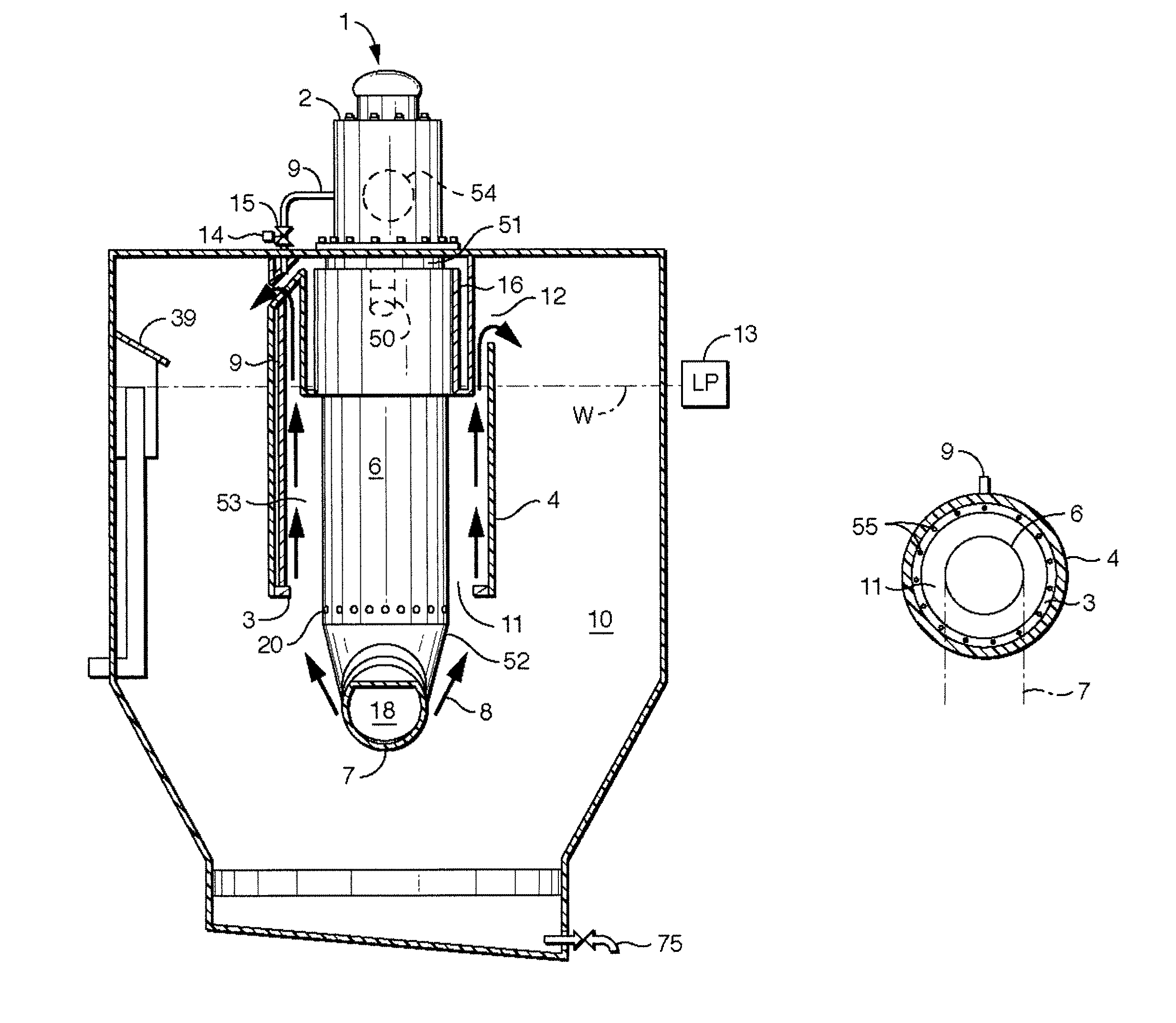
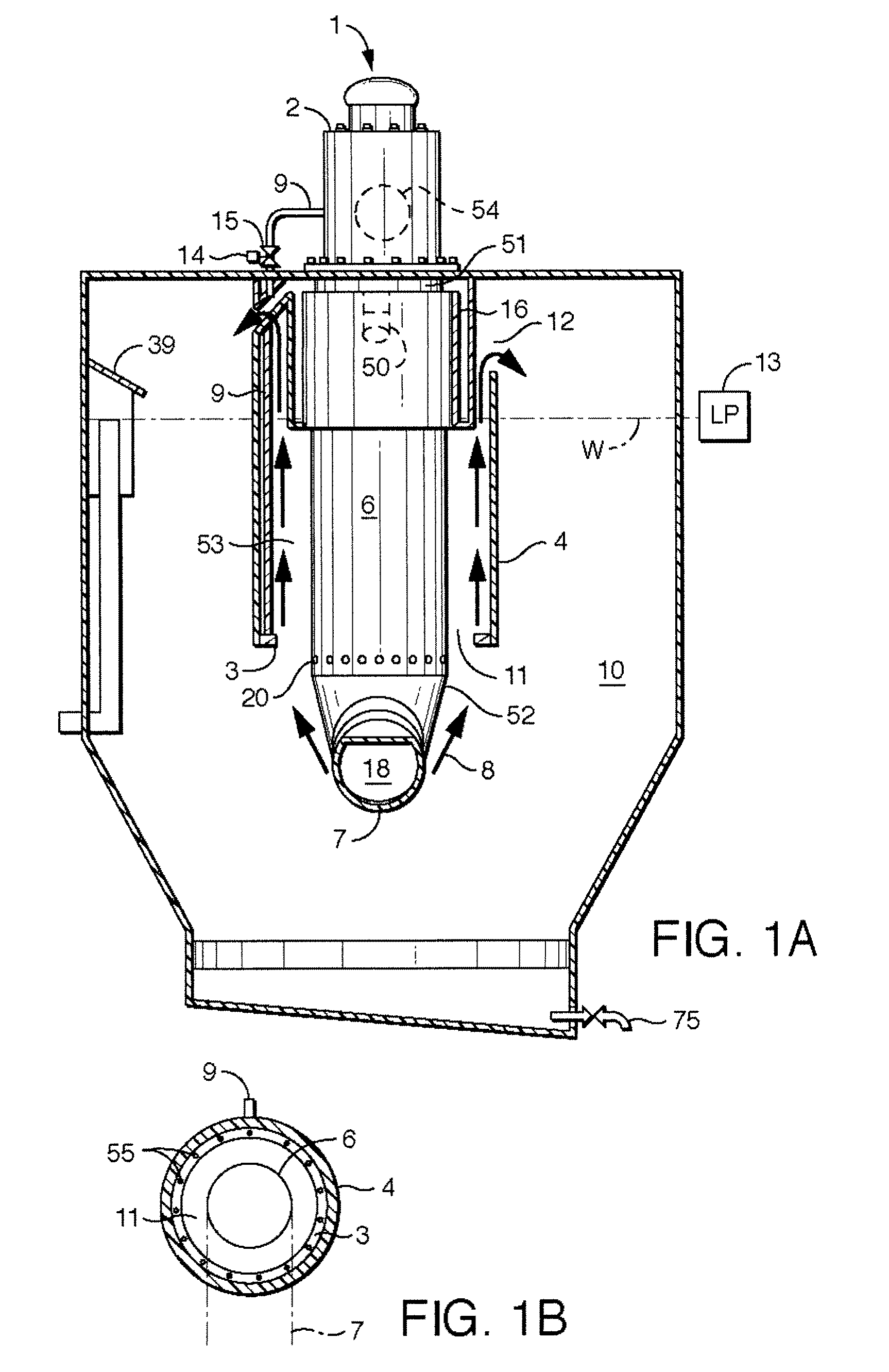
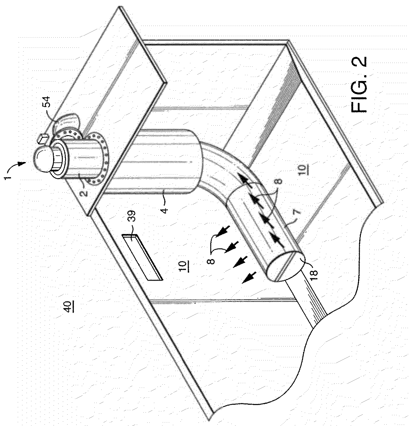
[0039]Snow melters used in snow removal typically incorporate more than one fuel burner to generate the heat required for melting collected snow. Such multiple fuel burner devices are in general bulky and cumbersome to use and transport, and substantially use more fuel than is needed for certain snow melting applications. The present invention overcomes these difficulties by providing a snow melter capable of a ‘snow start’ with a single burner assembly allowing for a smaller, more compact device which as a result of the single burner assembly utilizes less fuel.

[0040]The burner assembly (1) incorporates combustion chamber (6,7) comprising a downcomer tube (6) and a sparger tube (7). The downcomer tube (6) is affixed at the upper, or first end (51) thereof to a burner (2), and encloses a burner nozzle (50) of burner (2). The lower, or second end (52) of the downcomer tube (6) is joined to the sparger tube (7) in a substantially 90° orientation thereto. The sparger tube (7) has a ser...


PUM


Abstract

A single burner snow melter is capable of a snow start. The burner assembly has a fuel burner having adjustable combustion output and a nozzle through which products of combustion emerge, and a combustion chamber which has a first portion in substantially air-tight communication with the fuel burner and which encloses the nozzle. A second portion of the combustion chamber is shaped and dimensioned such that the second portion is placed into a snow melting receptacle or pit. The combustion chamber has a plurality of directional discharge means formed at least on its second portion through which products of combustion from the fuel burner emerge, and thus agitate, and melt snow loaded into a tank or pit. The burner assembly also includes an air cooling assembly for supplying air to cool at least the first portion of the combustion chamber.

Description

RELATED APPLICATION[0001]This application claims priority to Canadian Patent Application Number 2,651,636, filed Feb. 5, 2009, the entire contents of which are incorporated herein by reference.FIELD OF THE INVENTION[0002]The present invention relates to snow melting equipment, and more specifically, to improvements in traditional snow melters which utilize heat to melt and thus dispose of large amounts of snow. In particular, the invention relates to a single burner snow melting apparatus capable of a snow start operation.BACKGROUND OF THE INVENTION[0003]Snow melting devices known in the art commonly utilize a burner unit or assembly to provide heat to a snow melting medium, typically water. The heated medium is then used in various ways to melt the snow.[0004]Canadian Patent No. 780,673 and U.S. Pat. No. 3,187,743 (both to Primas) disclose a snow melting device commonly known in the art. This device includes a tank and a fuel burner assembly. The burner assembly includes a downward...

Claims


Application Information

Patent Timeline
Patent Type & Authority Patents(United States)
IPC IPC(8): E01C19/45
CPCE01H5/102
Inventor BURNETT, DAVIDBURNETT, GLENMEREDITH, STEVEN
Owner TRECAN COMBUSTION
Learn More