Right angle adaptor

a right angle and adaptor technology, applied in the field of backplane related connectors, can solve problems such as increasing rates, and achieve the effect of improving the electrical performance of the first connector

Active Publication Date: 2014-01-14
MOLEX INC
View PDF13 Cites 26 Cited by
  • Summary
  • Abstract
  • Description
  • Claims
  • Application Information

AI Technical Summary

Benefits of technology

[0006]An adaptor is configured to couple a first connector to a second connector while providing an angle change between the first and second connector. The adaptor includes a first and second recess that face in opposing directions and that are configured to receive the first and second connector. A floor can be provided in the adaptor to separate the first recess from the second recess. A pin array can be positioned in the floor and the pin array can extend in two directions from the floor so as to extend into the first and second recess. The pin array includes signal terminals and ground terminals. The signal terminals can be arranged in pairs so as to provide a differential signal channel. The signal terminals are configured with first and second contact ends that are respectively positioned in the first and second recess. The first and second contact ends can be respectively configured with a first and second orientation that are at a right angle with respect to each other. Therefore, a differential pair can have first contacts in a first line and second contacts can be in a second line that is at a right angle with respect to the first line. A body portion of the signal contacts can be configured to provide a transition between the first contact end and the second contact end. The body portion can also include a feature to engage the floor. Ground terminals can also be configured to provide first contacts in a first orientation and second contacts in a second orientation with the first and second orientation 90 degrees apart. To improve electrical performance of the first connector, a ground member can be inserted into the floor. The ground member can be configured to engage multiple ground terminals so as to common the ground terminals with respect to each other. In an embodiment, the adaptor can be configured to so that the first recess includes a first and second pin array. The first pin array may be configured as discussed above and the second pin array can include terminals that are configured with contact ends in the first recess and tails that extend out of the floor but are configured to engage vias in a mid-plane.

Problems solved by technology

Existing mid-plane designs, however, create problems as the data rates increase.

Method used


Image

  • Right angle adaptor
  • Right angle adaptor
  • Right angle adaptor

Examples


Embodiment Construction

[0043]The detailed description that follows describes exemplary embodiments and is not intended to be limited to the expressly disclosed combination(s). As can be appreciated, a number of features are being disclosed. It should be noted, however, that the disclosed features do not necessarily have to be used in the depicted configurations. Therefore, unless otherwise noted, features disclosed herein may be combined together to form additional combinations that were not otherwise shown for purposes of brevity. Furthermore, certain features can be combined but also may be used separately to provide a connector system that provides the desired balance between performance and cost. Thus, the depicted features have broad application.

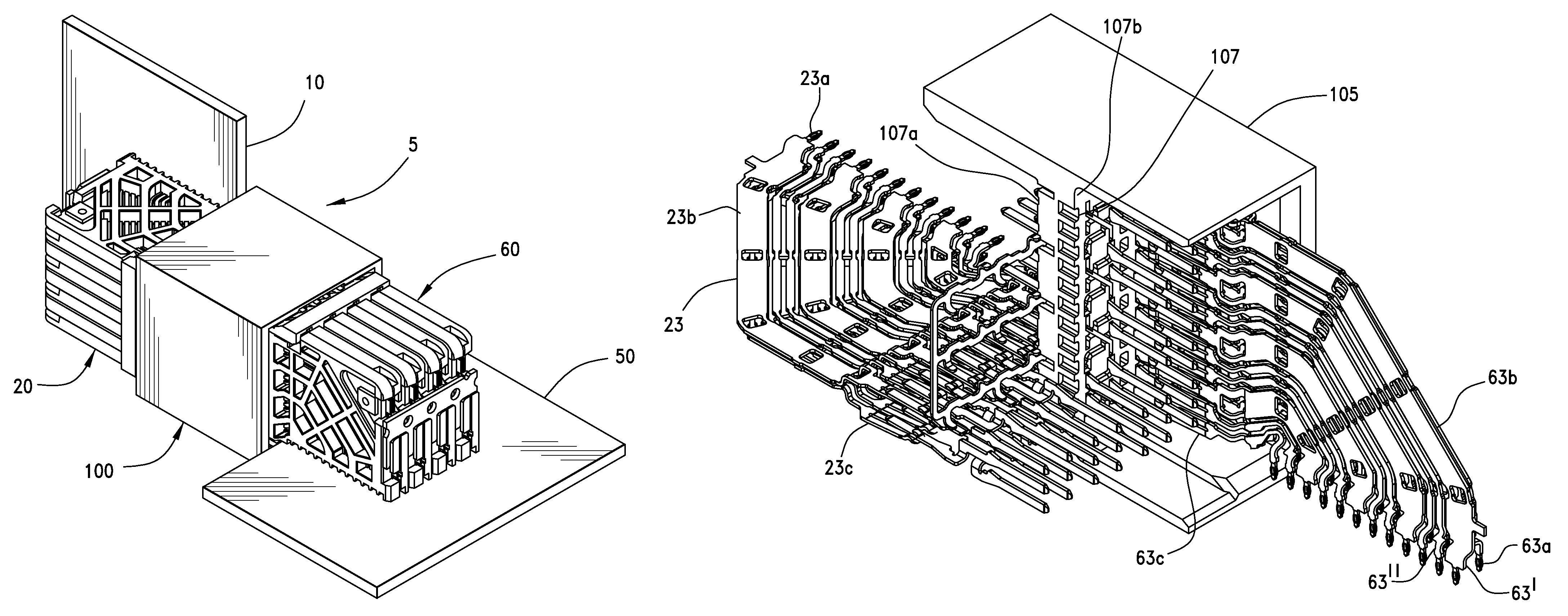
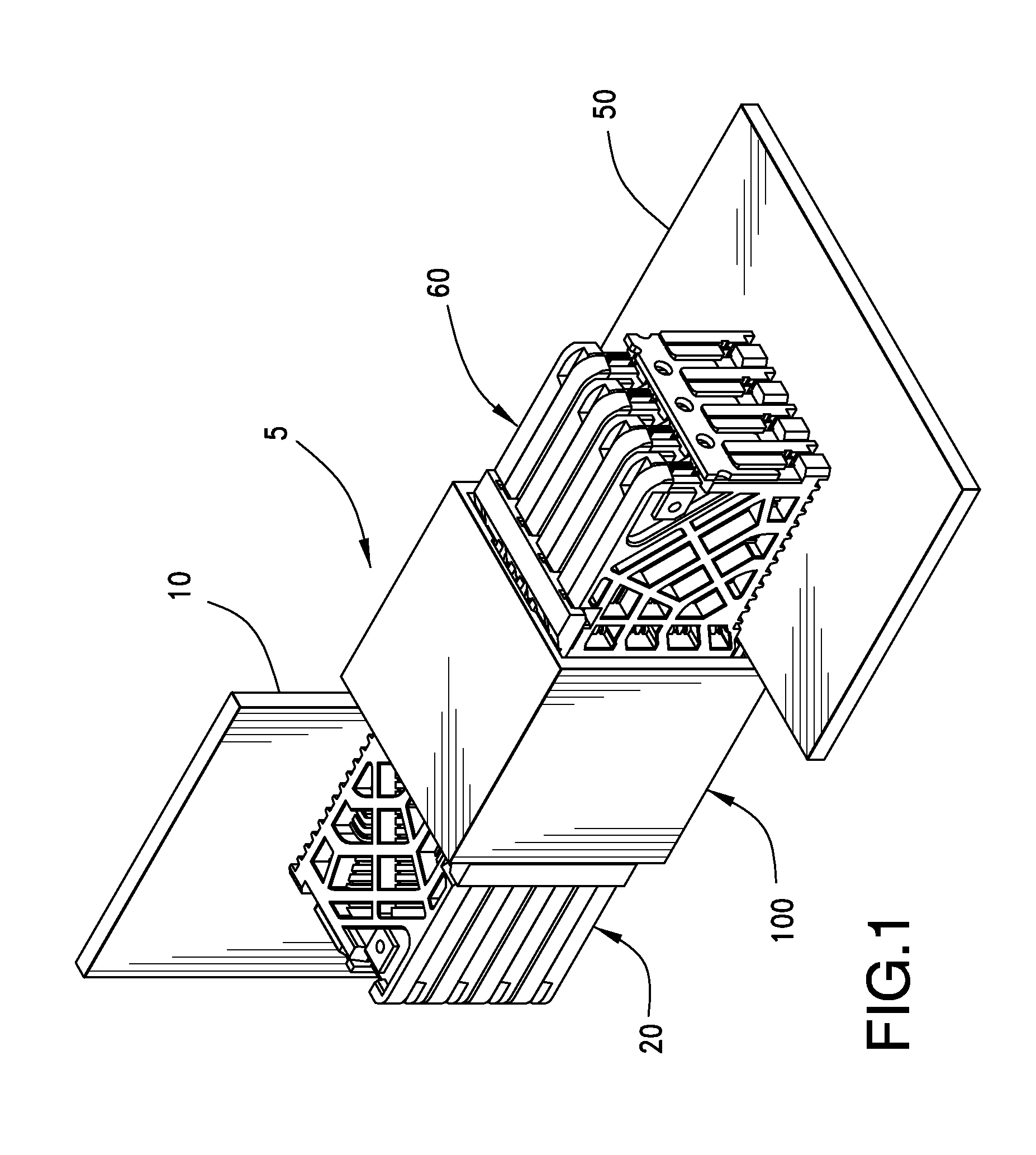
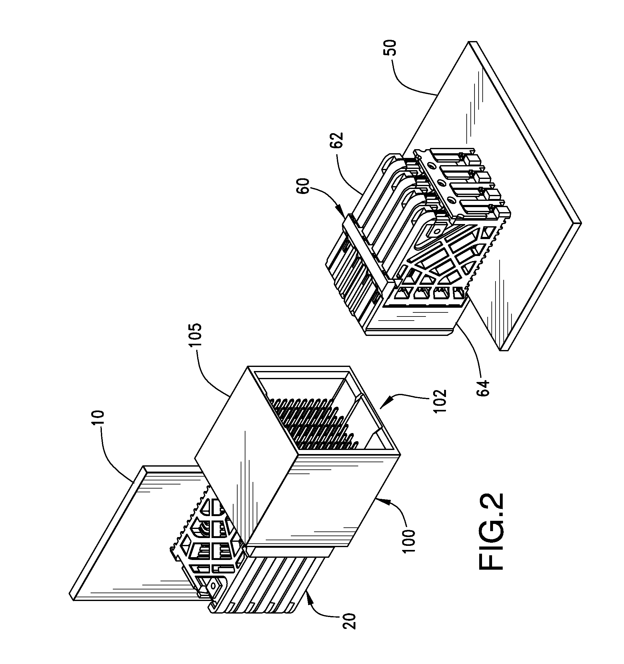
[0044]Looking first at FIGS. 1-4, an embodiment of connector system 5 that includes an adaptor 100 is depicted. The connector system 5 includes a first connector 20 that is coupled to a first side of the adaptor 100 and is mounted to a first board 10. The con...


PUM


Abstract

An adaptor includes a first and second recess that face in opposing directions and that are configured to receive a first and second connector. A floor in the adaptor can separate the first recess from the second recess. A pin array can be positioned in the floor and the pin array can extend in two directions from the floor so as to extend into the first and second recess. The pin array can include terminals that are configured with first and second contact ends that are respectively positioned in the first and second recess. The first and second contact ends can be respectively configured with a first and second orientation that are at a right angle with respect to each other.

Description

BACKGROUND OF THE INVENTION[0001]1. Field of the Invention[0002]The present invention relates to the field of connectors, more specifically to the field of backplane related connectors.[0003]2. Description of Related Art[0004]Backplane connectors are known. They are typically used to couple two separate boards (e.g., between a communication board and a processor board) so as to enable high speed communication between different portions of a computing system. In general, backplane connectors tend to offer dense pin fields and are configured for high data rates. For example, recent backplane designs have allowed data rates that are greater than 10 Gbps and new designs are intended to allow data rates of 20 Gbps or more.[0005]Typically backplane connectors are provided in what is known as a mezzanine configuration or an orthogonal configuration. Mezzanine connectors are used to couple together two boards that are parallel while orthogonal connectors couple boards that are positioned at...

Claims


Application Information

Patent Timeline
Patent Type & Authority Patents(United States)
IPC IPC(8): H01R31/06
CPCH01R13/6471H01R12/737H01R2107/00H01R31/06
Inventor LAURX, JOHN C.AMLESHI, PEEROUZHAUGE, BRIAN
Owner MOLEX INC
Why Eureka
Try Eureka