
Rotor assembly for a gas turbine

a gas turbine and rotor assembly technology, which is applied in the direction of liquid fuel engines, vessel construction, marine propulsion, etc., can solve the problems of increasing the risk of annulus filler detachment under centrifugal load, difficult and potentially time-consuming safe engagement of hooks, and hoop stress and circumferential crack propagation, so as to reduce the effect of clearance holes as stress raisers and reduce the risk of annulus filler detachment under circumferential load

Active Publication Date: 2014-01-28
ROLLS ROYCE PLC
View PDF27 Cites 3 Cited by
  • Summary
  • Abstract
  • Description
  • Claims
  • Application Information

AI Technical Summary

Benefits of technology

This solution reduces manufacturing costs, simplifies assembly, enhances the stability of annulus fillers under load conditions, and minimizes the risk of detachment during operation, while maintaining blade integrity and reducing stress crack propagation.

Problems solved by technology

Firstly, the need to form dedicated, load-bearing attachment features such as hooks on the outside of a forged fan rotor disc adds to the cost and complexity of manufacturing the fan rotor disc.
In addition, safely engaging the hooks with one another is difficult and potentially time-consuming because, in practice, the hooks tend to be obscured from view by the adjacent blades and by the annulus filler itself during assembly.
Failure safely to engage the hooks increases the risk of annulus filler detachment under a centrifugal load during rotation of the fan.
Tests have shown that annulus filler inserts secured using hook style arrangements such as the one described in International Application PCT / GB93 / 00372 are also vulnerable to detachment under these circumferential loads.

Method used


Image

  • Rotor assembly for a gas turbine
  • Rotor assembly for a gas turbine
  • Rotor assembly for a gas turbine

Examples


Embodiment Construction

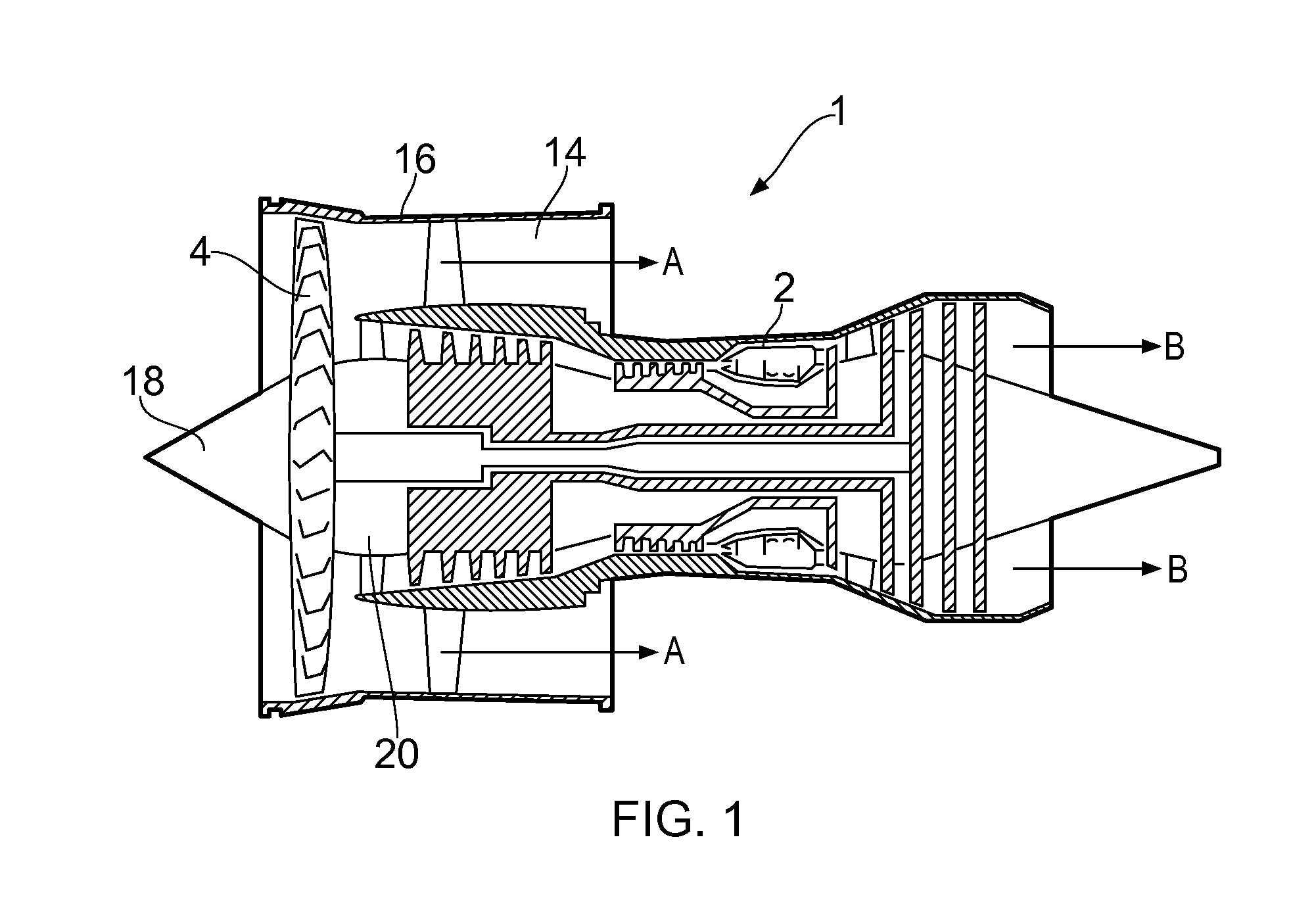
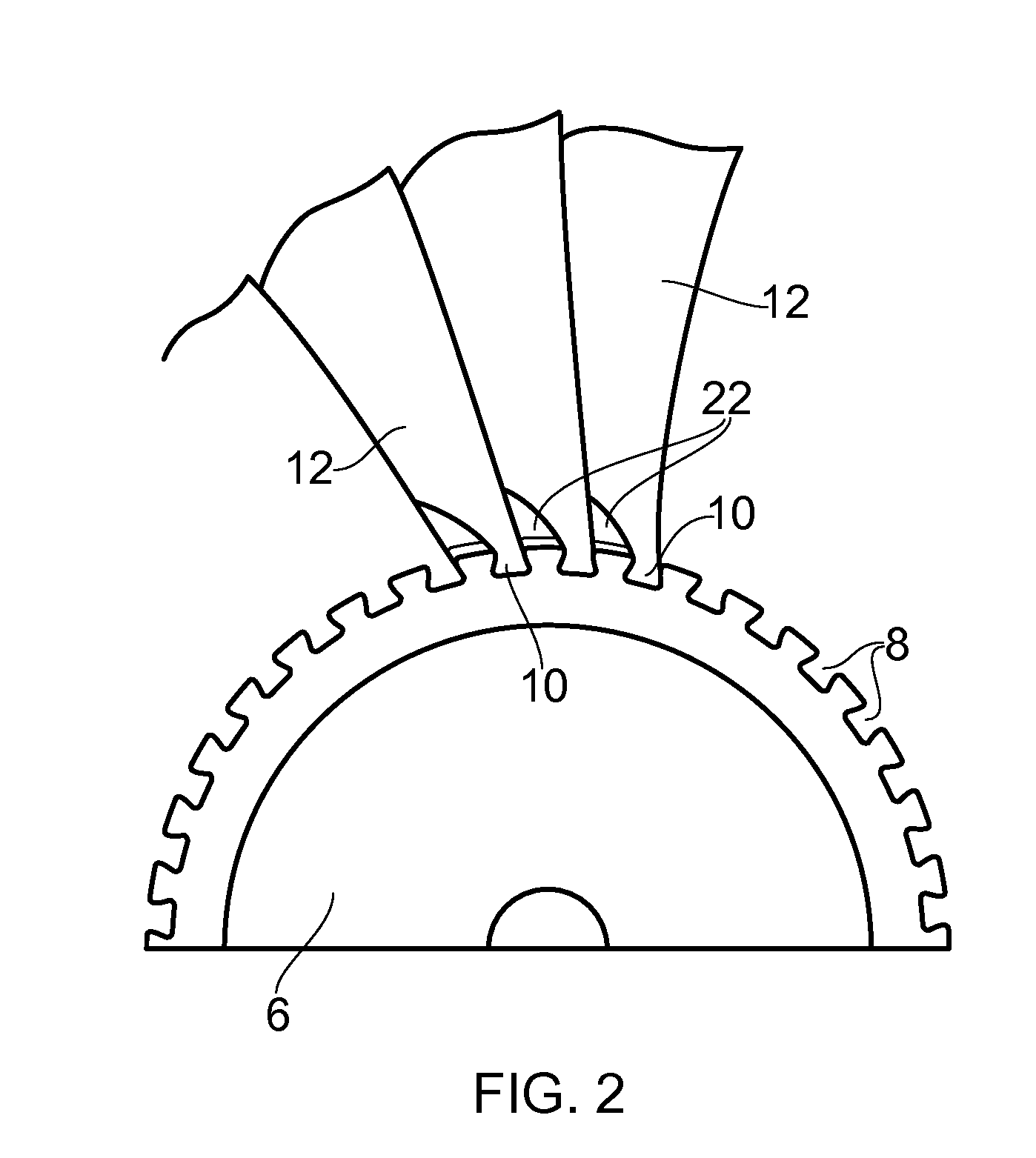
[0036]FIG. 1 shows a turbo fan engine 1 of generally conventional configuration comprising a core engine 2 which drives a fan 4 at the front of the engine 1. The fan 4 comprises a fan rotor disc assembly 6 (FIG. 2) having a circumferential array of axial dovetail slots 8, each of which receives the root 10 of a respective blade 12, there thus being provided a circumferential array of blades 12 around the fan 4.

[0037]As the fan 4 rotates, the blades 12 divert a portion of the intake flow into an annular bypass duct 14; this bypass flow A combines with the core exhaust flow B from the core engine 2 to provide propulsive thrust.

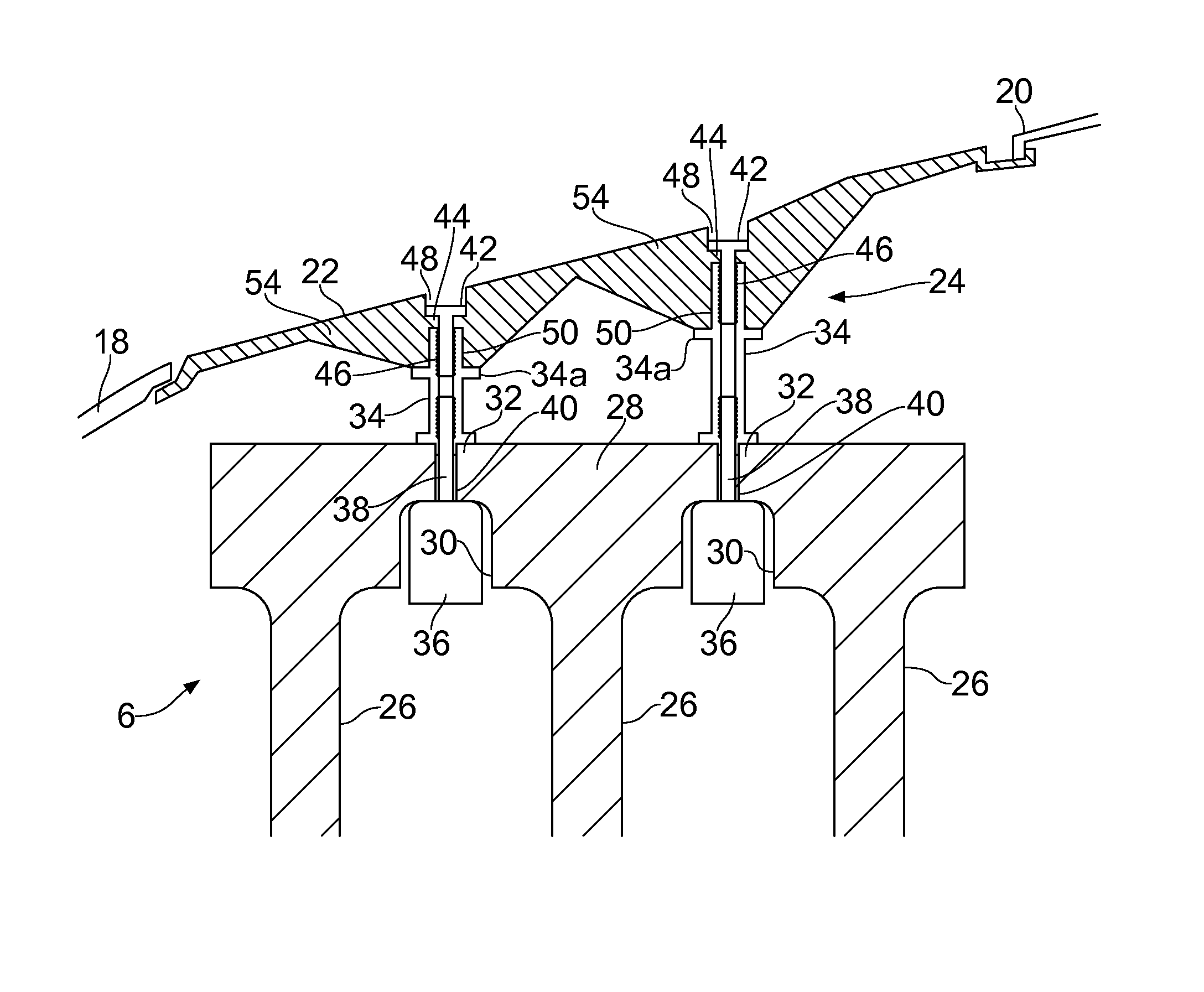
[0038]The bypass duct 14 is defined by a casing assembly 16, the front portion of which forms the outer wall of a flow annulus through the fan 4. The corresponding inner wall of the flow annulus through the fan 4 is provided immediately upstream of the fan 4 by a nose cone 18, immediately downstream of the fan 4 by a hub section 20 and, in between the blades 12 ...


PUM


Abstract

A rotor assembly, for a gas turbine, has a plurality of rotor discs interconnected by an axially extending rim. The outside of the rim has a circumferential array of dovetail slots and the underside of the rim has a circumferential channel which extends radially part way into the slots, the respective discs thus being interconnected axially across the channel by an array of circumferentially spaced connecting portions. There is an array of blades, each blade having a blade root secured in a respective one of the dovetail slots.

Description

CROSS REFERENCE TO RELATED APPLICATION[0001]This application is entitled to the benefit of British Patent Application No. GB 0914060.9, filed on Aug. 12, 2009.FIELD OF THE INVENTION[0002]The present invention relates to a rotor assembly for a gas turbine engine, in particular the bypass fan assembly of a turbo fan engine.BACKGROUND OF THE INVENTION[0003]A conventional turbo fan engine uses the core engine to drive a bypass fan mounted near the engine intake. Fan blades on the bypass fan drive a bypass flow around the core engine which combines downstream with the core exhaust flow to provide propulsive thrust.[0004]A casing assembly extends around the outside of the fan to provide an outer wall of a flow annulus through the fan. The fan blades themselves are not normally provided with blade platforms, and so a number of separate circumferential wall inserts or “annulus fillers” are mounted on the outside of the fan rotor disc, in-between the fan blades, to form the inner wall of the...

Claims


Application Information

Patent Timeline
Patent Type & Authority Patents(United States)
IPC IPC(8): F01D5/30
CPCF02K3/06F01D5/3007F01D5/06F01D11/008
Inventor EVANS, DALE, EDWARD
Owner ROLLS ROYCE PLC
Learn More