
Welding process

a welding process and arc welding technology, applied in the direction of machine/engine, manufacturing tools, welding apparatus, etc., can solve the problems of cf6-cf6-cf6-cf6-cf6-cf6-cf6-cf6-cf6-cf6-cf6-cf6-cf6-cf6-cf6-cf6-cf6-cf6-cf6-cf6-

Inactive Publication Date: 2005-11-29
GENERAL ELECTRIC CO
View PDF4 Cites 44 Cited by
  • Summary
  • Abstract
  • Description
  • Claims
  • Application Information

AI Technical Summary

Benefits of technology

The process reduces the risk of distortion and machining requirements, achieving suitable mechanical properties and fatigue strength while minimizing the number of passes needed for repair, thus improving efficiency and maintaining acceptable wall thickness.

Problems solved by technology

The support flange 18 inevitably requires replacement as a result of weld repairs performed on the frame 10 that cause distortion, resulting in the movement of the flange 18 to the extent that the dimensional limits of the flange 18 cannot be recovered.
However, due to the set back of the CDP seal flange 18 inside the frame 10 and the proximity of the outer casing wall 14, EB welding cannot be used to perform this type of weld repair on the CF6-50 frame 10.
Because of the limited penetration possible with conventional GTAW techniques, a butt joint is not used.
The requirement for multiple passes to build up the weldment 20 within the channel 22 is less than optimal in that performing such a repair is time consuming and often results in part distortions that can spawn a series of unplanned repairs.

Method used


Image

  • Welding process
  • Welding process
  • Welding process

Examples


Embodiment Construction

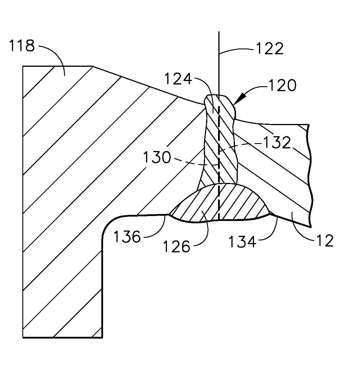
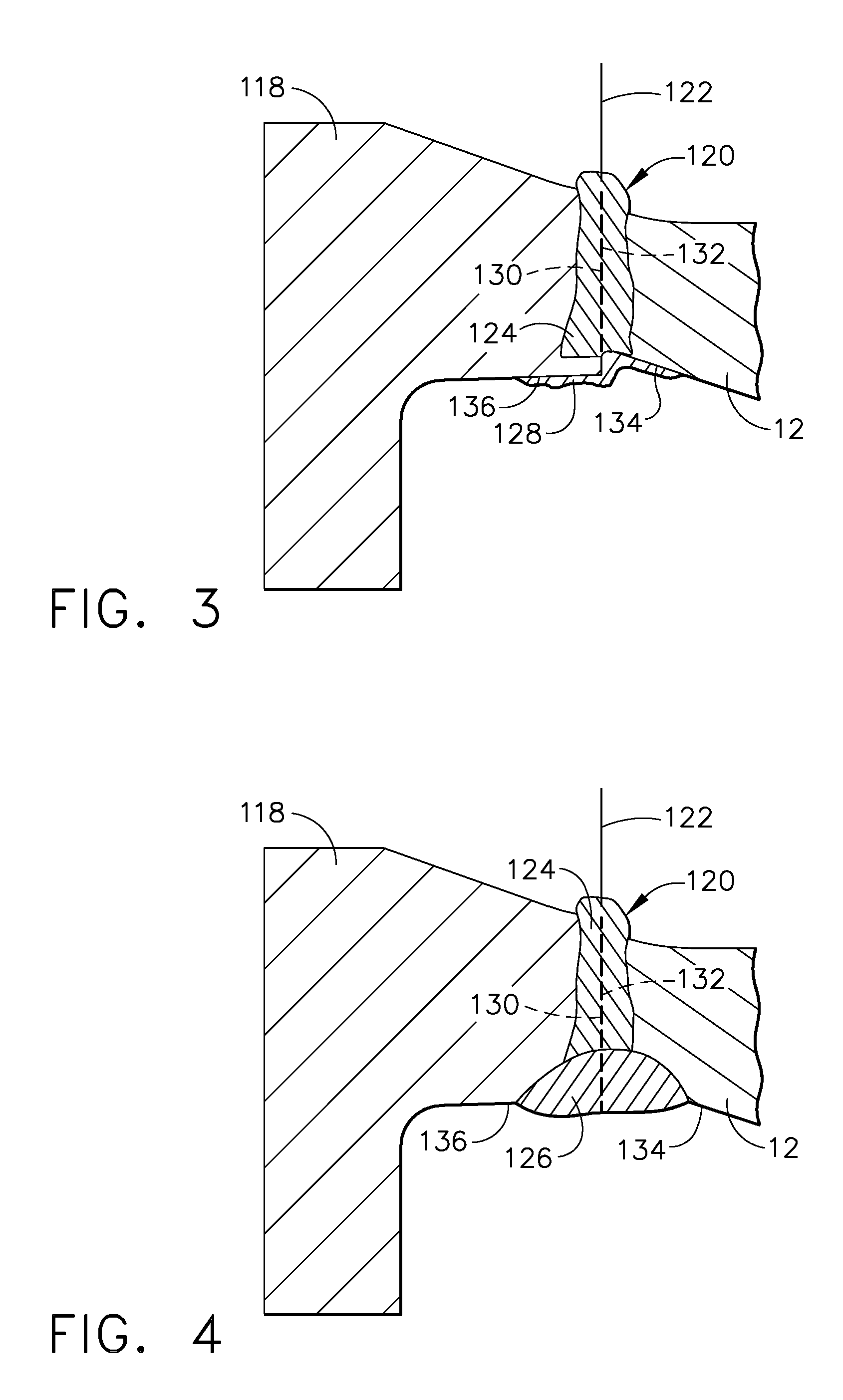
[0018]FIGS. 3 and 4 show a weld joint 120 formed between a replacement seal flange 118 and the forward end of an inner casing wall of a compressor rear frame (CRF). Similar to FIG. 2, FIGS. 3 and 4 are represented as details of the compressor rear frame 10 of FIG. 1, and therefore the inner casing wall is identified with reference number 12. The compressor rear frame 10 is preferably formed of a nickel-base superalloy, such as Inconel 718, though the invention is also applicable to welding of other components formed of various materials and for which weld penetration and quality are critical for achieving acceptable mechanical properties, including strength and fatigue life. As discussed in reference to FIG. 1, the frame 10 comprises a cylindrically-shaped inner casing wall 12 and a cylindrically-shaped outer casing wall 14 that substantially circumscribes the inner casing wall 12. The flange 118 of FIGS. 3 and 4 replaces the compressor discharge pressure (CDP) seal flange 18 of FIG...


PUM

PropertyMeasurementUnit
widthaaaaaaaaaa
widthaaaaaaaaaa
radial widthaaaaaaaaaa

Abstract

A process for repairing a compressor rear frame of a gas turbine engine. The process entails removing a seal flange from the inner casing wall of the frame to define an annular face on the casing wall, and fabricating a replacement flange to have an annular face with a radial width greater than the radial width of the annular face of the casing wall. The faces of the flange and wall are mated to form a joint, a penetration-enhancing flux is deposited adjacent the joint, and a single-pass gas tungsten arc welding operation is performed to form a root weldment that extends completely through the joint. The flux is then removed and a gas tungsten arc welding operation is performed to deposit a filler on the root weldment and form a second weldment that completely overlays but does not penetrate through the root weldment.

Description

BACKGROUND OF INVENTION[0001]1. Field of the Invention[0002]The present invention generally relates to welding equipment and processes. More particularly, this invention relates to an arc welding process for repairing a compressor rear frame (CRF) of a gas turbine engine.[0003]2. Description of the Related Art[0004]FIG. 1 schematically represents a compressor rear frame (CRF) 10 of the CF6-50 high-bypass gas turbine engine manufactured by the General Electric Company. The frame 10 can be seen as comprising inner and outer casing walls 12 and 14 interconnected by radially-extending struts 16. A support flange 18 located at the forward end of the inner casing wall 12 is adapted to carry a stationary seal, referred to as the compressor discharge pressure (CDP) seal (not shown). When the frame 10 is installed in an engine, the CDP seal is positioned in close proximity to a seal disk (not shown) mounted on a shaft that interconnects the high pressure turbine and compressor of the engine....

Claims


Application Information

Patent Timeline
Patent Type & Authority Patents(United States)
IPC IPC(8): B23K9/00F02C7/00B23K9/02B23K9/16B23K9/167B23K9/235B23K31/00B23K35/362B23K103/08B23P15/04F04D29/42
CPCB23K9/0216B23K9/167B23K9/235B23P6/005F01D5/005Y10T29/49318F05D2230/235B23K2201/001B23K2101/001
Inventor TREWILER, GARY EDWARDPEACOCK, DARYLHARRISON, WILLIAM HENRY
Owner GENERAL ELECTRIC CO
Learn More