Printing apparatus

a technology of printing apparatus and printing medium, which is applied in the direction of printing presses, instruments, printing, etc., can solve the problems of inefficient conversion of current, degraded quality of printed matter, and inability to dry the print medium in sufficient time, so as to achieve the effect of less power consumption

Inactive Publication Date: 2014-02-04
CANON KK
View PDF3 Cites 3 Cited by
  • Summary
  • Abstract
  • Description
  • Claims
  • Application Information

AI Technical Summary

Benefits of technology

[0010]Thus, in view of the above-described circumstances, an object of the present invention is to provide a printing apparatus that can heat a print medium using a heat pump with less power consumption.
[0012]According to the present invention, a print medium is heated utilizing the heat quantity of hotter superheated steam and can thus be heated to a higher temperature. This enables the print medium to be heated in a short time. Furthermore, the insufficiency of heat dissipation from a condenser can be reduced to allow a stable refrigeration cycle to be maintained. Thus, the power consumption of a heat pump can be reduced to allow an energy saving effect to be improved.

Problems solved by technology

This precludes a sufficient time to dry the print medium and to provide dry ink on the print medium.
As a result, the quality of printed matter may be degraded.
However, a conversion of current into heat is likely to result in a loss.
Hence, in general, electric energy generated by current is not very efficiently converted into heat energy, leading to a relatively low heat efficiency of the heating source.
As described above, the heat of the superheated steam cannot be effectively used, and thermal efficiency is thus insufficient.
This leads to extra driving of a compressor and the possible consumption of extra power.
Furthermore, the print medium cannot obtain a sufficient amount of heat dissipated from the condenser.
Thus, the maintenance of such a state for a long time results in insufficient heat dissipation from the condenser.
This prevents a stable refrigeration cycle from being maintained, and increases the operating pressure of the compressor.
The operating pressure and power consumption of the compressor are in an almost proportional relationship, and the heat pump thus consumes increased power.

Method used


Image

  • Printing apparatus
  • Printing apparatus
  • Printing apparatus

Examples


first embodiment

(First Embodiment)

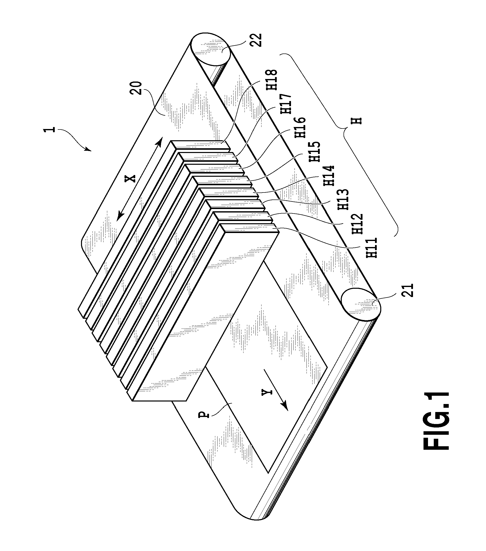
[0028]FIG. 1 is a perspective view schematically showing an example of a full-line ink jet printing apparatus applied to an embodiment of the present invention. An ink jet printing apparatus 1 includes a plurality of elongate print heads H11 to H18, each with a plurality of ejection portions (hereinafter referred to as nozzles) arranged in array configured to eject ink; the print heads H11 to H18 correspond to plural types of inks in the respective colors. Furthermore, an endless conveying belt 20 serving as a conveying section for conveying a print medium P is provided in a direction crossing an x direction that is a longitudinal direction of the print heads (direction along which the ejection port array is extended). The conveying belt 20 is passed around two rollers 21 and 22. When one of the rollers is continuously rotated by a driving motor (not shown in the drawings), the conveying belt 20 moves cyclically to continuously convey the print medium in a Y direct...

second embodiment

(Second Embodiment)

[0055]Now, a second embodiment of the present invention will be described. In the figures, components of the second embodiment which are configured as is the case with the first embodiment are denoted by the same reference numerals. The description of these components is omitted, and only different components will be described.

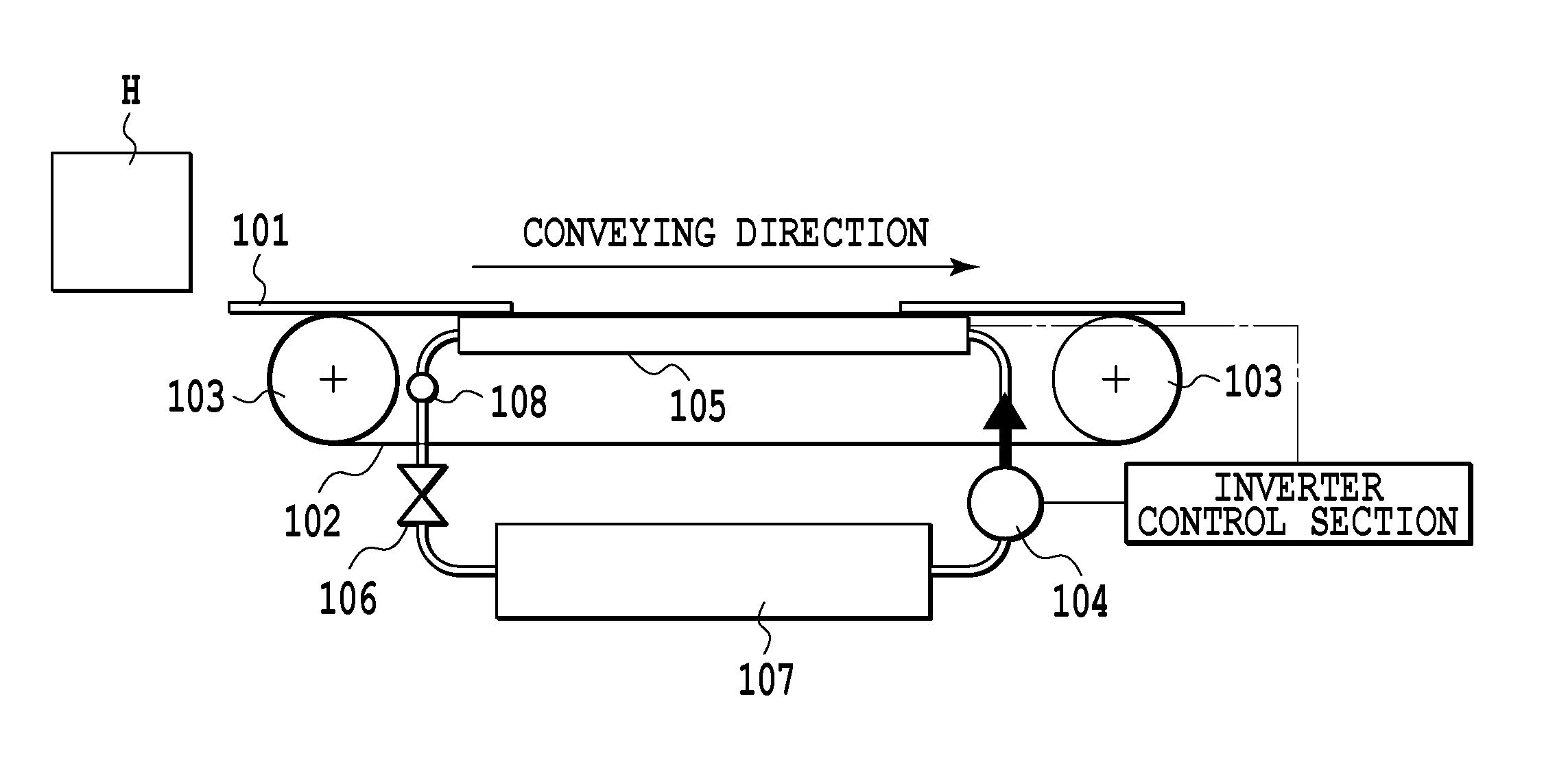
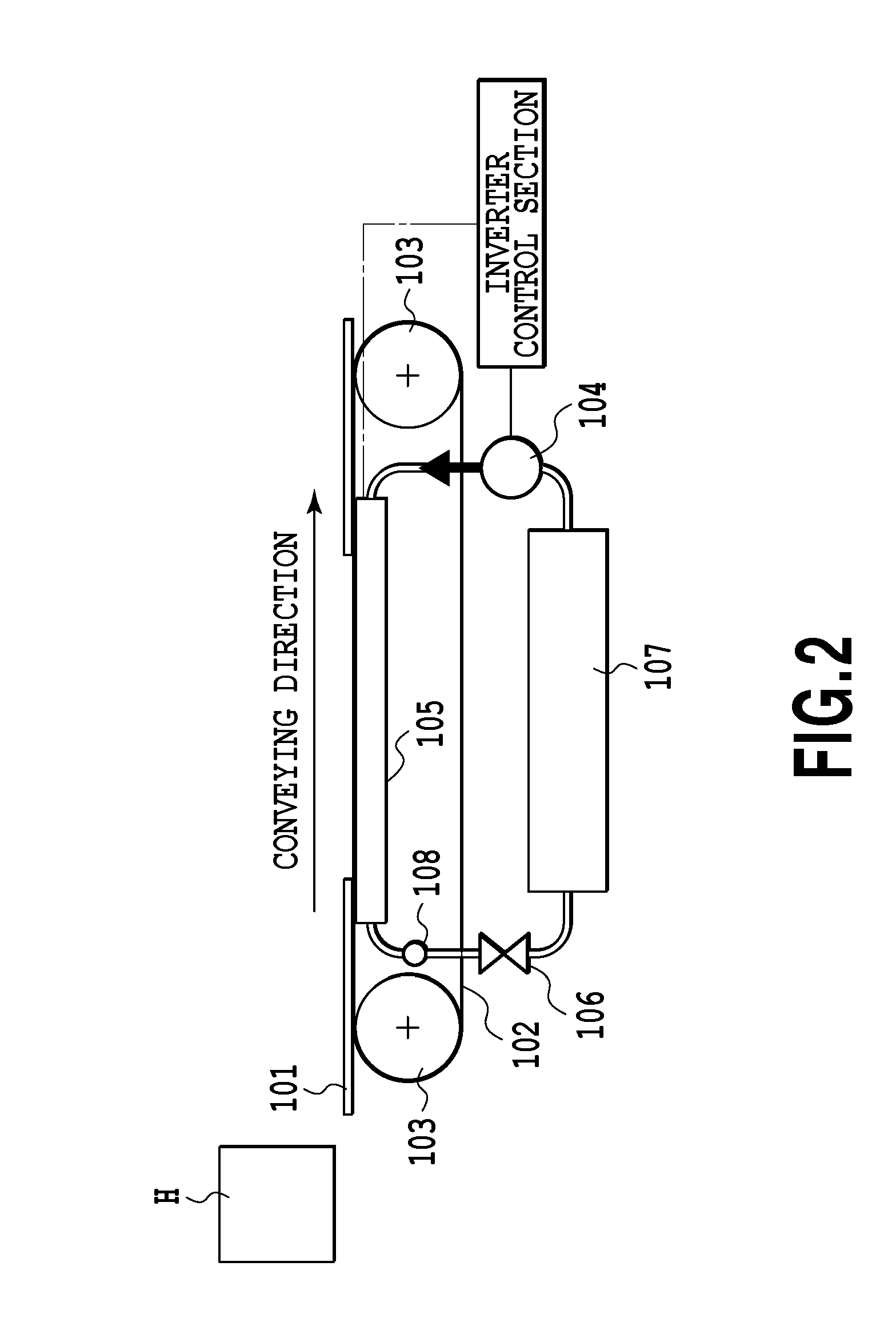
[0056]FIG. 10 is a cross-sectional view schematically showing the configuration of heating and drying unit for heating a print medium 101 printed with ink by print heads in the second embodiment. A heat-pump mechanism according to the second embodiment is different from that according to the first embodiment in that the former heat pump includes two separate condensers 105a and 105b. In the second embodiment, the condenser 105 is separated into the condenser 105a on the refrigerant-outlet side thereof, where a refrigerant changed into wet steam flows out from the condenser, and the condenser 105b on the refrigerant-inlet side thereof, where ...


PUM


Abstract

A printing apparatus allows a print medium to be heated to a temperature equal to or higher than a condensation temperature of a refrigerant when the print medium is heated during a condensation process of a heat pump. The printing apparatus includes a heating unit for heating a print medium, and a conveying unit for conveying the print medium which has been heated by the heating unit. The heating unit includes a heat-pump mechanism. The heating unit heats the print medium by transferring heat generated by a condenser when the refrigerant is condensed by the condenser. The refrigerant flows along a conveying direction in which the print medium is conveyed by the conveying unit, and flows into the condenser at a downstream side thereof in the conveying direction and out from the condenser at an upstream side thereof in the conveying direction.

Description

BACKGROUND OF THE INVENTION[0001]1. Field of the Invention[0002]The present invention relates to a printing apparatus with heating unit for heating printed print media.[0003]2. Description of the Related Art[0004]In image formation based on ink jet printing, an image is formed on a print medium by ejecting ink onto the print medium. When printing is performed according to such an ink jet method at high speed, immediately after a printed print medium is placed at a sheet discharging position, the next printed print medium may reach the sheet discharging position. This precludes a sufficient time to dry the print medium and to provide dry ink on the print medium. Thus, a printed image portion of the first printed print medium may come into contact with the second printed print medium. Furthermore, when a printed print medium is laid on top of a preceding printed print medium immediately after the preceding printed print medium has been discharged, ink may adhere to the back side of th...

Claims


Application Information

Patent Timeline
Patent Type & Authority Patents(United States)
IPC IPC(8): B41F23/04
CPCB41J11/002B41J11/0024
Inventor TAKAHATA, KAZUAKI
Owner CANON KK
Why Eureka
Try Eureka