Plug-in connection having shielding

a shielding and plug-in connection technology, applied in the direction of coupling devices, two-part coupling devices, coupling device connections, etc., can solve the problems of not being able to achieve optimal signal behavior in such a connector, not easily possible to further miniaturize, and not easy to enable densely packed arrangement of signal and shielding contact elements. , to achieve the effect of increasing the stability of particularly sensitive males

Active Publication Date: 2014-02-04
ERNI PRODION GMBH
View PDF19 Cites 17 Cited by
  • Summary
  • Abstract
  • Description
  • Claims
  • Application Information

AI Technical Summary

Benefits of technology

[0013]This object is achieved by a plug-in connection with shielding of the kind mentioned above in such a way that adjacent contact groups are arranged in adjacent columns offset from one another by a predeterminable length dimension, with the length dimension corresponding approximately to half the distance of two adjacent contact groups in a column. As a result, not only a maximally possible distance is achieved between the contact groups in one column and the contact groups in an adjacent column so that further miniaturization of the signal contacts can be achieved, but it is also possible by an enlargement of the distance of signal contacts arranged in adjacent columns to achieve a further increase in the data transmission rate to 25 gigabits per second or more. It is a further important advantage that as a result of this respectively offset arrangement of adjacent contact groups in adjacent columns intermediate spaces are produced between the contact groups which can be used on the one hand for arranging stabilizing elements in the plug housing and on the other hand also for improving the shielding between adjacent contact columns, as will be explained below in closer detail.
[0016]Such an arrangement is only enabled by the offset arrangement of the contact groups in adjacent columns. Only this ensures that even in the case of compact and further miniaturized configuration there will not be any contact between the pair of differential contacts and the contact springs of the shielding plates. As a result of the offset arrangement, the contact springs of the shielding plates are as far away as possible from the pairs of differential contacts. It is further advantageously provided for this purpose that the shielding plates are provided with a thinner configuration in the region of the bent tapering contact springs. This improves the spring effect on the one hand and takes the limited overall space into account on the other hand.
[0019]An especially advantageous configuration provides that reinforcing ribs are arranged in the male multipoint connector housing in the region of the respectively offset contact groups in which a cavity is formed. As a result, such reinforcing ribs are respectively provided on both sides of the contact group columns, which reinforcing ribs are respectively offset by one column width to the left and the right. These reinforcing ribs enable a substantial increase in the stability of the especially sensitive male multipoint connector housing.

Problems solved by technology

This arrangement in conjunction with the L-shaped shielding elements that do not completely shield the signal contacts and their arrangement do not allow any disturbance-free signal transmission in the very high frequency range.
Such an arrangement does not easily enable a densely packed arrangement of the signal and shielding contact elements.
Moreover, the signal behavior is not optimal in such a connector.
As a result of the straight arrangement of the contact groups in rows and columns, further miniaturization is not easily possible.
In particular, an increase in the data transmission rate is not easily possible.
Furthermore, it has proven to be disadvantageous in such connectors that as a result of their filigree configuration they often do not have the required stability which enable the repeated plugging and detaching of the two plug-in elements of male multipoint connector and female multipoint connector in an easy fashion.

Method used


Image

  • Plug-in connection having shielding
  • Plug-in connection having shielding
  • Plug-in connection having shielding

Examples


Embodiment Construction

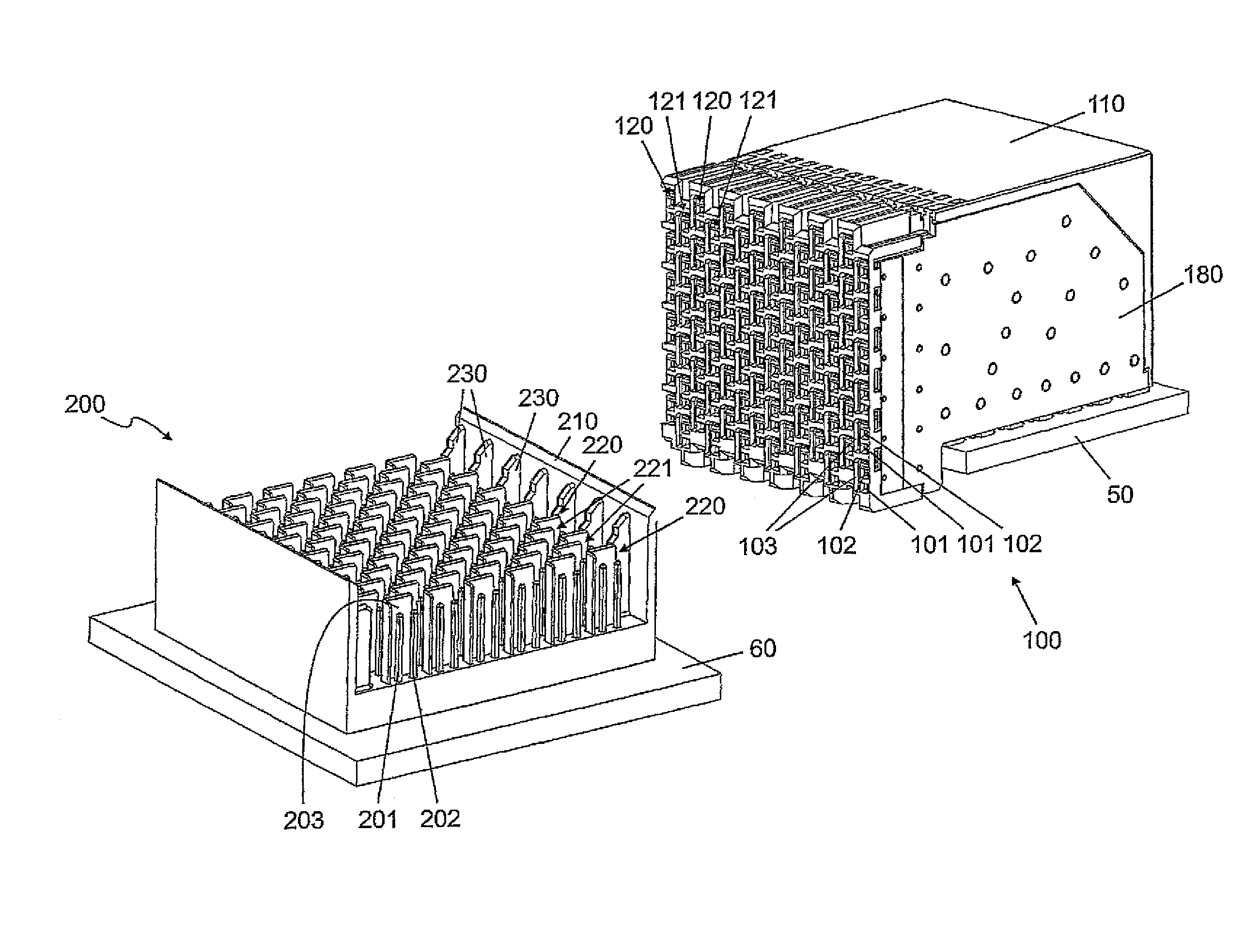
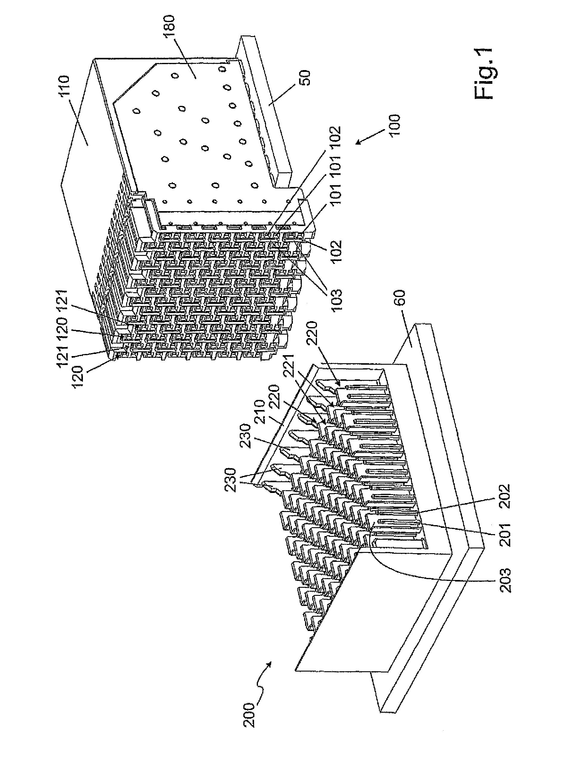
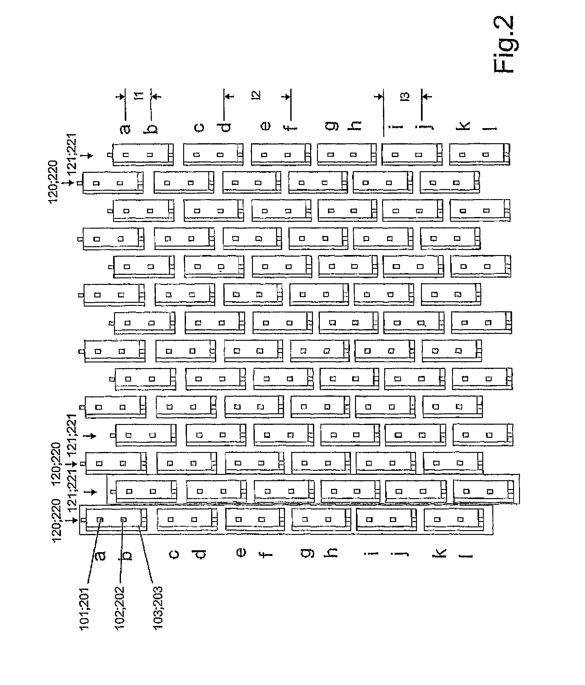
[0033]FIG. 1 shows a female multipoint connector 100 in the right half of the drawing, which female multipoint connector is fixed to and in contact with a circuit board 50 by means of soldered or pressed connections for example. The female multipoint connector comprises a plurality of contact group columns 120 on its front side, which columns are respectively arranged in parallel with respect to each other. Every contact group column 120 comprises a plurality of differential contact pairs 101, 102 which are arranged above one another and which are respectively enclosed by an L-shaped shielding plate 103. Two differential contacts 101, 102 and the associated shielding plate 103 respectively form one contact group. The plug therefore consists of a plurality of contact group columns and contact group rows, with the contact group rows being characterized in such a way that adjacent contact groups in an adjacent contact group column are respectively arranged in an offset manner by a pred...


PUM


Abstract

The invention relates to a plug-in connection having shielding, in particular a multi-pin, multi-row plug-in connection comprising a male multipoint connector and a female multipoint connector, the plug-in connection comprising signal contacts, which are arranged in a contact pattern of differential pairs and which form a contact group together with an L-shaped shielding element that surrounds the signal contacts, the contact groups being arranged in rows and columns and adjacent contact groups in adjacent columns being offset from each other by a specifiable length dimension in the longitudinal direction of the columns, the plug-in connection being characterized in that the specified length dimension corresponds to approximately half the distance of two adjacent contact groups in a column.

Description

CROSS REFERENCE TO RELATED APPLICATIONS[0001]This application is the National Stage of PCT / DE2010 / 001055 filed on Sep. 8, 2010, which claims priority under 35 U.S.C. §119 of German Application No. 10 2009 040 487.2 filed on Sep. 8, 2009, the disclosure of which is incorporated by reference. The international application under PCT article 21(2) was not published in English.[0002]The invention relates to a plug-in connection with shielding, especially a multi-pin, multi-row plug-in connection consisting of a male multipoint connector and a female multipoint connector, which respectively comprise signal contacts which are arranged in contact patterns of differential pairs and which form a contact group together with an L-shaped shielding element that surrounds said signal contacts, with the contact groups being arranged in rows and columns and adjacent contact groups in adjacent columns being offset from each other by a predeterminable length dimension in the longitudinal direction of ...

Claims


Application Information

Patent Timeline
Patent Type & Authority Patents(United States)
IPC IPC(8): H01R13/648
CPCH01R12/585H01R13/514H01R23/688H01R23/7073H01R13/6587H01R12/716H01R12/724H01R13/6471H01R12/71H01R12/712H01R12/714H01R13/518H01R13/658H01R13/6581H01R13/6582H01R13/6583
Inventor LAPPOEHN, JUERGEN
Owner ERNI PRODION GMBH
Why Eureka
Try Eureka