Driving force transmission apparatus and vehicle

a technology of driving force transmission and transmission apparatus, which is applied in mechanical actuated clutches, transportation and packaging, and gearing, etc., can solve the problems of limited torque transmission capacity of clutches and difficulty in ensuring the load bearing of inner clutch plates, and achieve the effect of suppressing abnormal nois

Active Publication Date: 2014-02-04
JTEKT CORP
View PDF21 Cites 6 Cited by
  • Summary
  • Abstract
  • Description
  • Claims
  • Application Information

AI Technical Summary

Benefits of technology

[0008]It is an object of the invention to provide a driving force transmission apparatus and a vehicle in which generation of abnormal noise is suppressed even when the circumferential width of each protrusion of inner clutch plates spline-fitted to an inner rotating member is not smaller than the circumferential width of each protrusion of a pressing member for pressing a clutch spline-fitted to the inner rotating member.
[0010]According to the aspect of the invention, it is possible to suppress generation of abnormal noise even when the circumferential width of each protrusion of the inner clutch plates spline-fitted to the inner rotating member is not smaller than the circumferential width of each protrusion of a second cam member.

Problems solved by technology

Therefore, it is difficult to ensure the load bearing of the inner clutch plates, and the torque transmission capacity of the clutch may be limited.

Method used


Image

  • Driving force transmission apparatus and vehicle
  • Driving force transmission apparatus and vehicle
  • Driving force transmission apparatus and vehicle

Examples


first embodiment

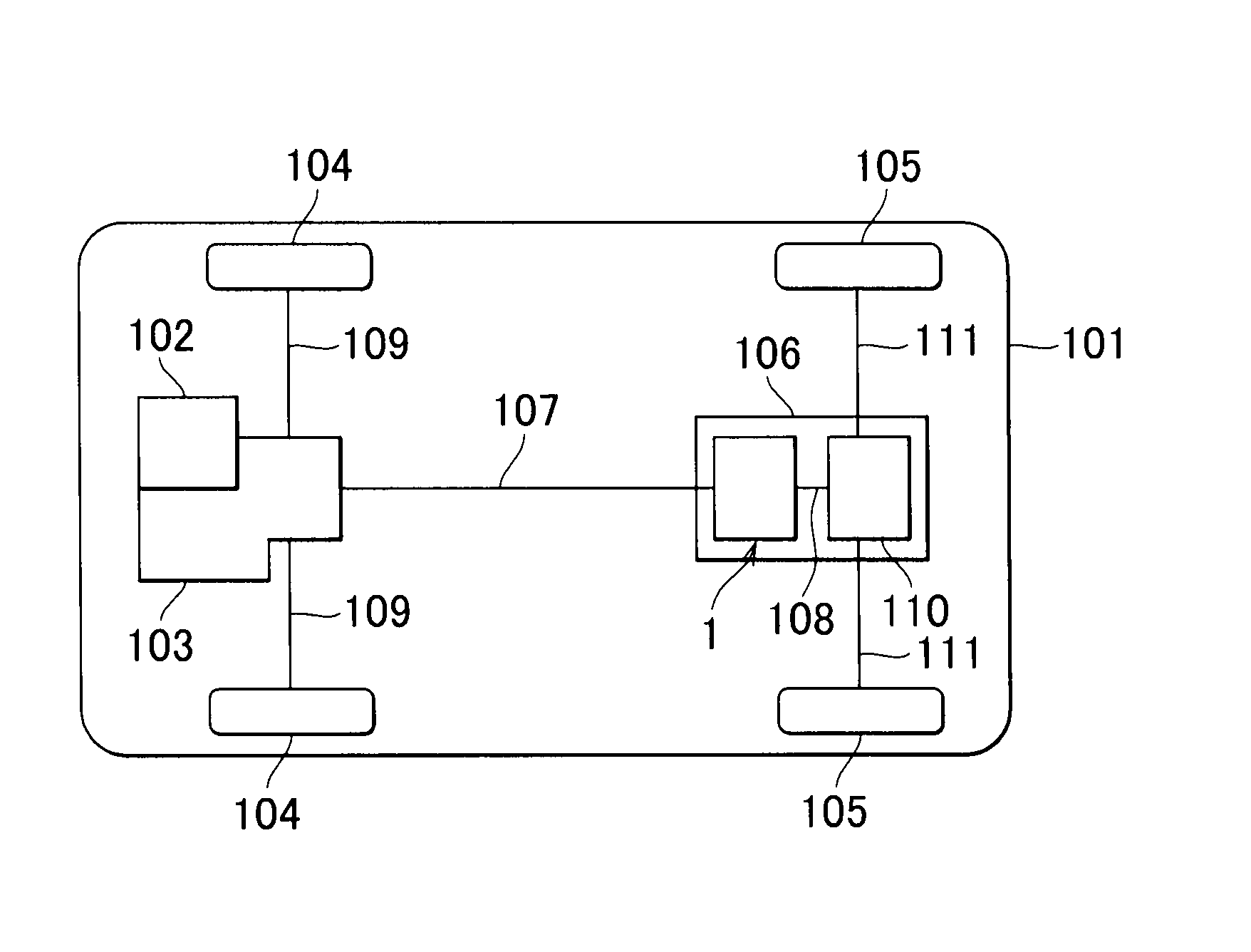
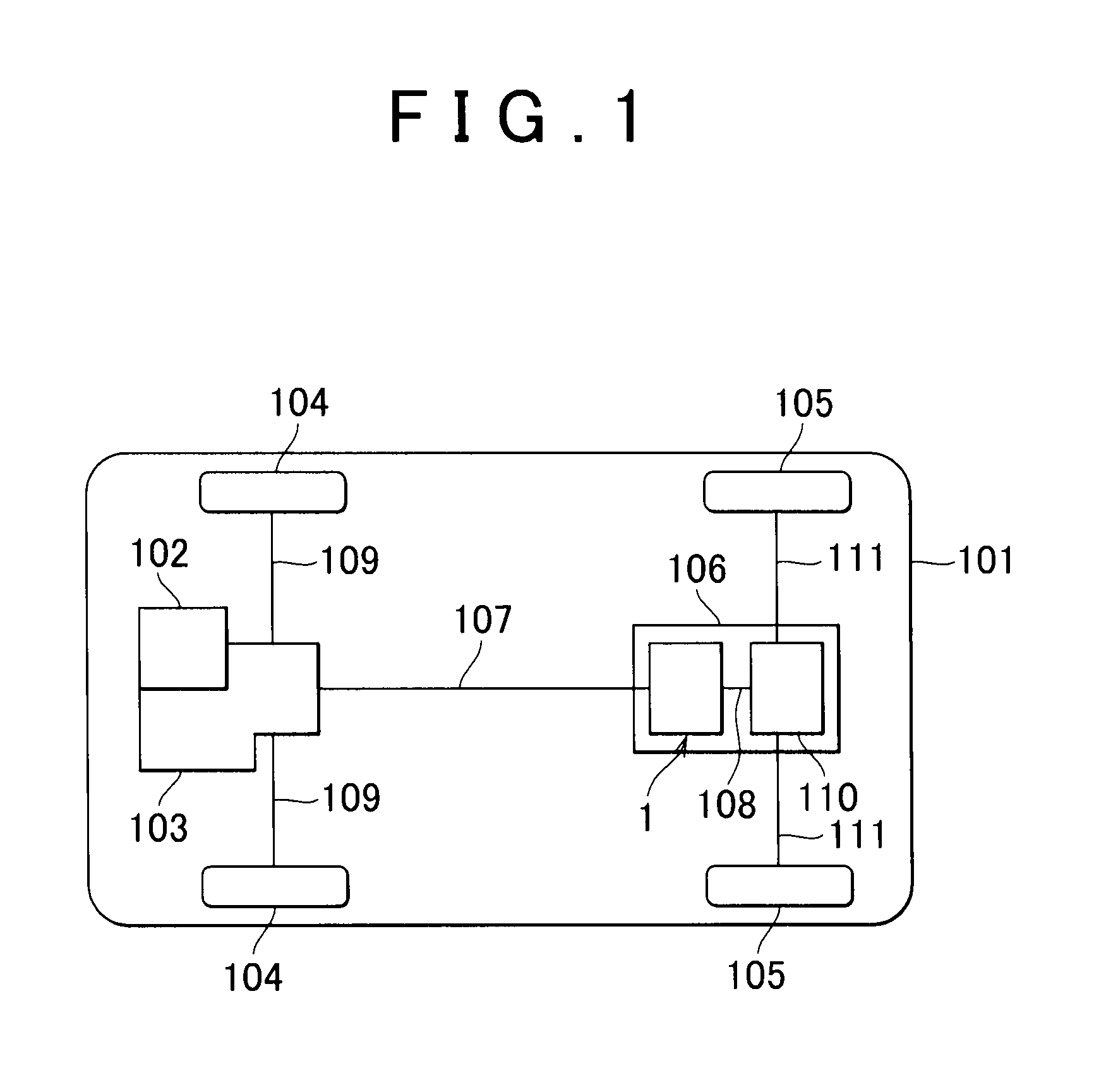
[0021]FIG. 1 is a schematic view that shows the configuration of a four-wheel drive vehicle 101 according to the invention. As shown in FIG. 1, the four-wheel drive vehicle 101 includes a driving force transmission apparatus 1, an engine 102 that serves as a driving source, a transaxle 103, a pair of front wheels 104, and a pair of rear wheels 105.

[0022]The driving force transmission apparatus 1 is arranged in a driving force transmission path extending from the front wheels to the rear wheels in the four-wheel drive vehicle 101, and is supported by a vehicle body (not shown) of the four-wheel drive vehicle 101 via a differential carrier 106.

[0023]The driving force transmission apparatus 1 couples a propeller shaft 107 to a drive pinion shaft 108 such that torque is transmittable, and is configured to be able to transmit the driving force from the engine 102 to the rear wheels 105 when the propeller shaft 107 and the drive pinion shaft 108 are coupled to each other. The details of t...

second embodiment

[0101]Operations and effects of the second embodiment will be described. When the four-wheel drive vehicle 101A accelerates or runs at a constant speed while moving straight ahead, torque is transmitted from the housing 2 of each of the driving force transmission apparatuses 1R and 1L to the inner shaft 3. At this time, the main cam 70, the inner shaft 3, the inner clutch plates 40, the outer clutch plates 41 and the outer housing 8 are, for example, engaged in the state shown in FIG. 5A. When the four-wheel drive vehicle 101A turns to the left from this state, the right rear wheel 105R rotates at a higher speed than the left rear wheel 105L, so the inner shaft 3 rotates at a higher speed than the housing 2 in the driving force transmission apparatus 1R. As a result, differential rotation between the housing 2 and inner shaft 3 of the driving force transmission apparatus 1R is reversed, and the members are, for example, engaged in the initial reverse state shown in FIG. 5B and then ...


PUM


Abstract

A driving force transmission apparatus includes: a front housing and an inner shaft coaxially with each other and rotatable relative to each other; a main clutch transmitting torque between the front housing and the inner shaft; and a cam mechanism having a main cam and a pilot cam and using the main cam to press the main clutch. Where a circumferential gap angle between each spline tooth of the front housing and a corresponding first protrusion of outer clutch plates is θ1, a circumferential gap angle between each spline tooth of the inner shaft and a corresponding protrusion of inner clutch plates is θ2 and a circumferential gap angle between each spline tooth of the inner shaft and a corresponding protrusion of the main cam is θ3, the inequality θ1+θ2−θ3≧1.0° is satisfied.

Description

INCORPORATION BY REFERENCE[0001]The disclosure of Japanese Patent Applications No. 2010-192462 filed on Aug. 30, 2010 and No. 2010-225905 filed on Oct. 5, 2010, including the specification, drawings and abstract, is incorporated herein by reference in its entirety.BACKGROUND OF THE INVENTION[0002]1. Field of the Invention[0003]The invention relates to a driving force transmission apparatus and a vehicle equipped with a driving force transmission apparatus.[0004]2. Description of Related Art[0005]In an existing art, there is known a driving force transmission apparatus for a vehicle, which includes an outer rotating member, an inner rotating member that is located coaxially with the outer rotating member and that is rotatable relative to the outer rotating member, a clutch that is formed of outer clutch plates spline-fitted to the outer rotating member and inner clutch plates spline-fitted to the inner rotating member, and a cam mechanism that presses the clutch (see, for example, Ja...

Claims


Application Information

Patent Timeline
Patent Type & Authority Patents(United States)
IPC IPC(8): F16H48/20
CPCF16D27/004F16D13/683F16D27/115Y10T74/19074
Inventor KOKUBO, NAOYUKI
Owner JTEKT CORP
Why Eureka
Try Eureka