
Structure and method for metal gate stack oxygen concentration control using an oxygen diffusion barrier layer and a sacrificial oxygen gettering layer

a technology of oxygen diffusion barrier layer and oxygen concentration control, which is applied in the direction of transistors, electrical equipment, semiconductor devices, etc., can solve the problems of difficult to increase the fabrication cost and complexity of metal gates in nmos and pmos transistors without significantly increasing fabrication costs and achieve the effect of increasing the effective work function

Active Publication Date: 2014-02-04
TEXAS INSTR INC
View PDF3 Cites 17 Cited by
  • Summary
  • Abstract
  • Description
  • Claims
  • Application Information

AI Technical Summary

Benefits of technology

The invention provides a process for making an integrated circuit with both NMOS and PMOS transistors. The process includes forming different gate metal layers in each type of transistor to achieve effective work functions that optimize their performance. The work function layers are oxidized to increase their effectiveness in the PMOS transistors and a getter material is used to extract oxygen from the NMOS work function layers to reduce their effectiveness. The result is an integrated circuit with improved performance and reliability.

Problems solved by technology

Attaining desired effective work functions of the metal gates in both NMOS and PMOS transistors without significantly increasing fabrication cost and complexity has been problematic.

Method used


Image

  • Structure and method for metal gate stack oxygen concentration control using an oxygen diffusion barrier layer and a sacrificial oxygen gettering layer
  • Structure and method for metal gate stack oxygen concentration control using an oxygen diffusion barrier layer and a sacrificial oxygen gettering layer
  • Structure and method for metal gate stack oxygen concentration control using an oxygen diffusion barrier layer and a sacrificial oxygen gettering layer

Examples


first embodiment

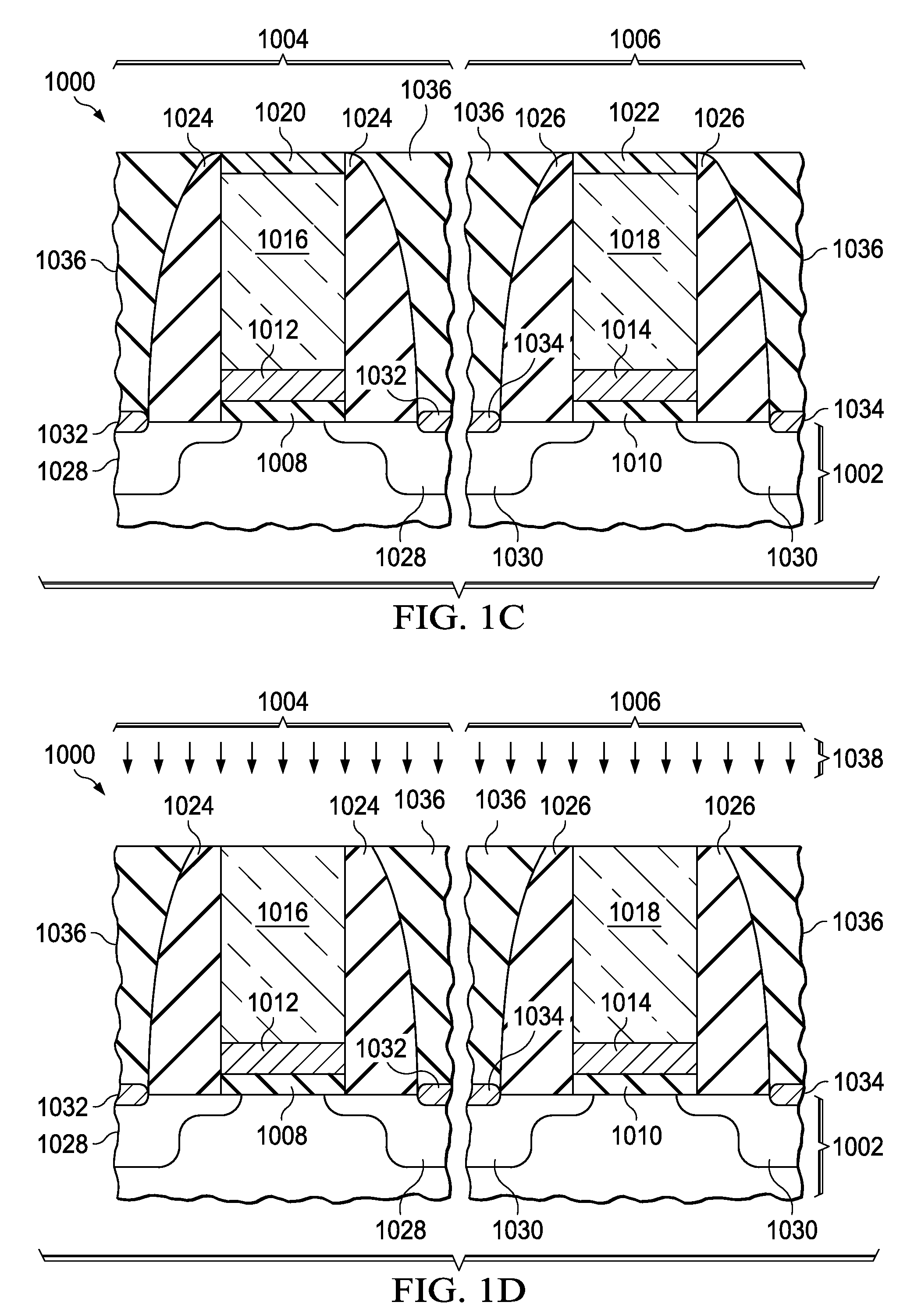
[0031]In the low temperature oxidation process, the integrated circuit (1000) may be exposed to a steam ambient between 300° C. and 600° C. for 10 seconds to 30 minutes, as described in U.S. Patent Provisional Application 61 / 116,892, filed Nov. 21, 2008 hereby incorporated by reference. In an alternate embodiment, the integrated circuit may be exposed to a steam ambient between 900° C. and 1100° C. for less than 1 second, as described in the aforementioned U.S. Patent Provisional Application.

second embodiment

[0032]In the low temperature oxidation process, the integrated circuit (1000) may be exposed to a plasma containing oxygen and hydrogen at a temperature up to 500° C., as described in the aforementioned US Patent Provisional Application. In an alternate embodiment, the integrated circuit may be exposed to a plasma containing oxygen, and subsequently exposed to a plasma containing hydrogen, as described in the aforementioned US Patent Provisional Application.

third embodiment

[0033]In the low temperature oxidation process, the gate work function metal layers (1012, 1014) may be anodized at a temperature up to 100° C., as described in the aforementioned US Patent Provisional Application.


PUM

PropertyMeasurementUnit
work functionaaaaaaaaaa
thickaaaaaaaaaa

Abstract

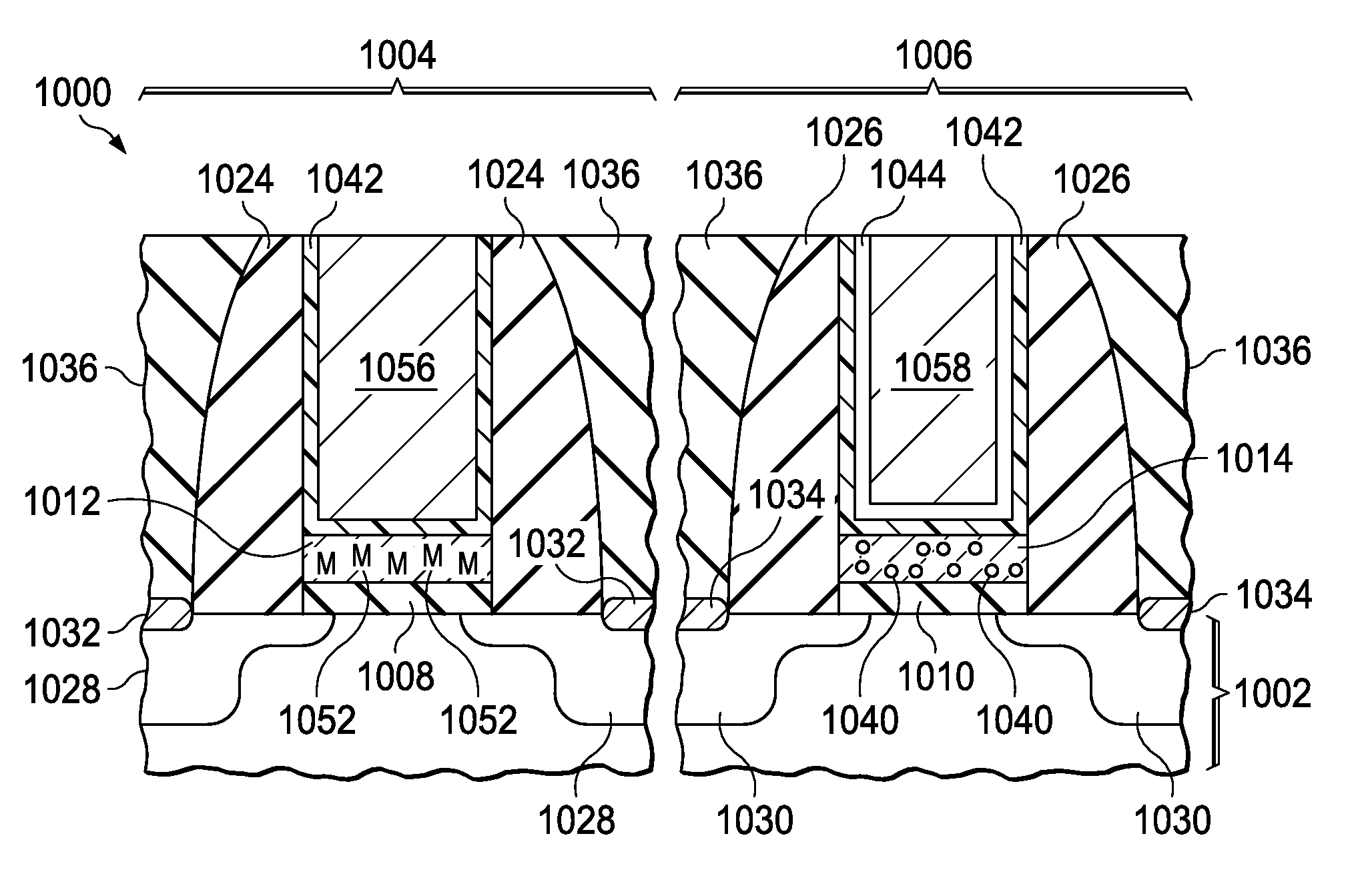
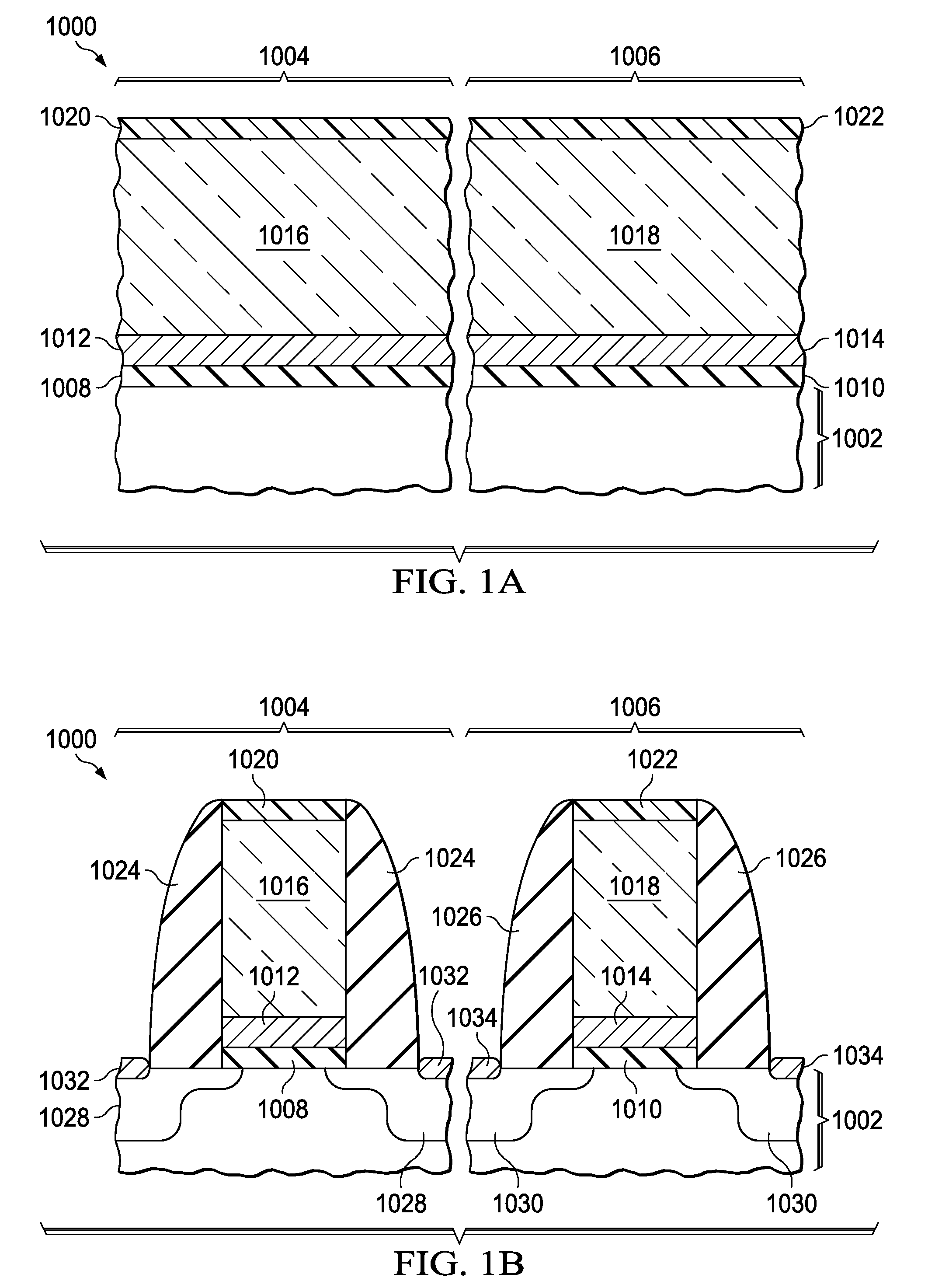
A process is disclosed of forming metal replacement gates for NMOS and PMOS transistors with oxygen in the PMOS metal gates and metal atom enrichment in the NMOS gates such that the PMOS gates have effective work functions above 4.85 eV and the NMOS gates have effective work functions below 4.25 eV. Metal work function layers in both the NMOS and PMOS gates are oxidized to increase their effective work functions to the desired PMOS range. An oxygen diffusion blocking layer is formed over the PMOS gate and an oxygen getter is formed over the NMOS gates. A getter anneal extracts the oxygen from the NMOS work function layers and adds metal atom enrichment to the NMOS work function layers, reducing their effective work functions to the desired NMOS range. Processes and materials for the metal work function layers, the oxidation process and oxygen gettering are disclosed.

Description

CROSS-REFERENCE TO RELATED APPLICATIONS[0001]The following patent application is related and hereby incorporated by reference: U.S. Patent Provisional Application 61 / 116,892, filed Nov. 21, 2008).FIELD OF THE INVENTION[0002]This invention relates to the field of integrated circuits. More particularly, this invention relates to replacement metal gates of MOS transistors in integrated circuits.BACKGROUND OF THE INVENTION[0003]N-channel metal oxide semiconductor (NMOS) and p-channel metal oxide semiconductor (PMOS) transistors in advanced integrated circuits frequently have replacement metal gates to improve on-state current densities. Attaining desired effective work functions of the metal gates in both NMOS and PMOS transistors without significantly increasing fabrication cost and complexity has been problematic.SUMMARY OF THE INVENTION[0004]The instant invention provides a process for forming an integrated circuit which includes NMOS and PMOS transistors with metal replacement gates...

Claims


Application Information

Patent Timeline
Patent Type & Authority Patents(United States)
IPC IPC(8): H01L21/70H10B10/00
CPCH01L21/28185H01L29/51H01L21/823842H01L29/66545H01L21/28088H01L29/7833H01L21/823857H01L21/823807H01L21/823814H01L27/092H01L27/11H01L29/401H10B10/00H01L21/3221H01L29/42364H01L29/517H01L29/518
Inventor CHAMBERS, JAMES JOSEPHNIIMI, HIROAKI
Owner TEXAS INSTR INC
Learn More