System and method for periodic body scan differencing

a technology of periodic body scan and differencing, applied in the field of computer systems, can solve the problems of insufficient use of morphological tissue imaging, poor resolution of mri's with respect to morphological tissue imaging for small details, and inability to achieve morphological tissue imaging. to achieve the effect of improving the detection of morphological changes

Inactive Publication Date: 2014-02-04
PASSMORE CHARLES G
View PDF20 Cites 6 Cited by
  • Summary
  • Abstract
  • Description
  • Claims
  • Application Information

AI Technical Summary

Benefits of technology

[0015]Embodiments may utilize surface or subsurface scans for difference calculations. Any type of scanner employing any scanning technology may be utilized wherein the scanner scans to the desired resolution of morphological testing. For example, use of an optical coherence tomography scanner allows for surface or subsurface scans down to a centimeter or so into the body with extremely high resolution on the order of a micron. This type of scanner allows for detecting morphological changes in geometry or visual appearance or both. When a portion of the skin has changed in geometry, e.g., a mole has become larger, yet has not changed in color, the geometry differences displayed by embodiments of the invention enable detection of possible problems that a standard visual examination or side by side comparison of photographs would simply miss. Use of a multispectral scanner allows for differences in cell types to be more readily observed in certain applications. Embodiments of the invention allow for differences in subsurface PET scans to be differenced with display of morphological changes over time highlighted. This allows for more thorough PET scan analysis compare to side by side visual comparison by a doctor for example.
[0017]Embodiments may also display morphological surface or subsurface differences between scans in multiple images or atlas view. Atlas view allows for one image to display the entire portion of the body scanned and makes for more rapid observation of differences. The depth of the images or atlas view depends on the scanning technology employed for the particular application. Any type of projection may be utilized in transforming the scan for visual display. For example, Mercator, equirectangular, gnomonic or any other projection such as cylindrical, pseudocylindrical for example may be utilized to create the atlas view.
[0020]Regardless of the type of scanning technology utilized, embodiments of the invention radically improve the detection of morphological changes in a body over time.

Problems solved by technology

Backscatter devices have been controversial in their proposed use for airport security due to the invasion of privacy, i.e., of a scanner capable of viewing through clothing for example.
The United States Food and Drug administration currently does not recommend whole body CT scanning as the radiation risks are thought to outweigh the remote possibility of detecting a disease early enough to cure the disease.
Hence, there are limitations with this type of technology with respect to morphological tissue imaging.
MRI's have poor resolution with respect to morphological tissue imaging for small details.
This imaging technique lacks millimeter penetration depth and is not utilized in morphological tissue imaging.
Ultrasound has poor resolution with respect to morphological tissue imaging.
Depending on the type of imaging technology and resulting images, many dangerous tissue changes go undetected based on the visual acuity of the particular doctor manually comparing the two images side by side.

Method used


Image

  • System and method for periodic body scan differencing
  • System and method for periodic body scan differencing
  • System and method for periodic body scan differencing

Examples


Embodiment Construction

[0035]A system and method for periodic body scan differencing for detecting changes in surface and subsurface body scans over time will now be described. In the following exemplary description numerous specific details are set forth in order to provide a more thorough understanding of embodiments of the invention. It will be apparent, however, to an artisan of ordinary skill that the present invention may be practiced without incorporating all aspects of the specific details described herein. In other instances, specific features, quantities, or measurements well known to those of ordinary skill in the art have not been described in detail so as not to obscure the invention. Readers should note that although examples of the invention are set forth herein, the claims, and the full scope of any equivalents, are what define the metes and bounds of the invention.

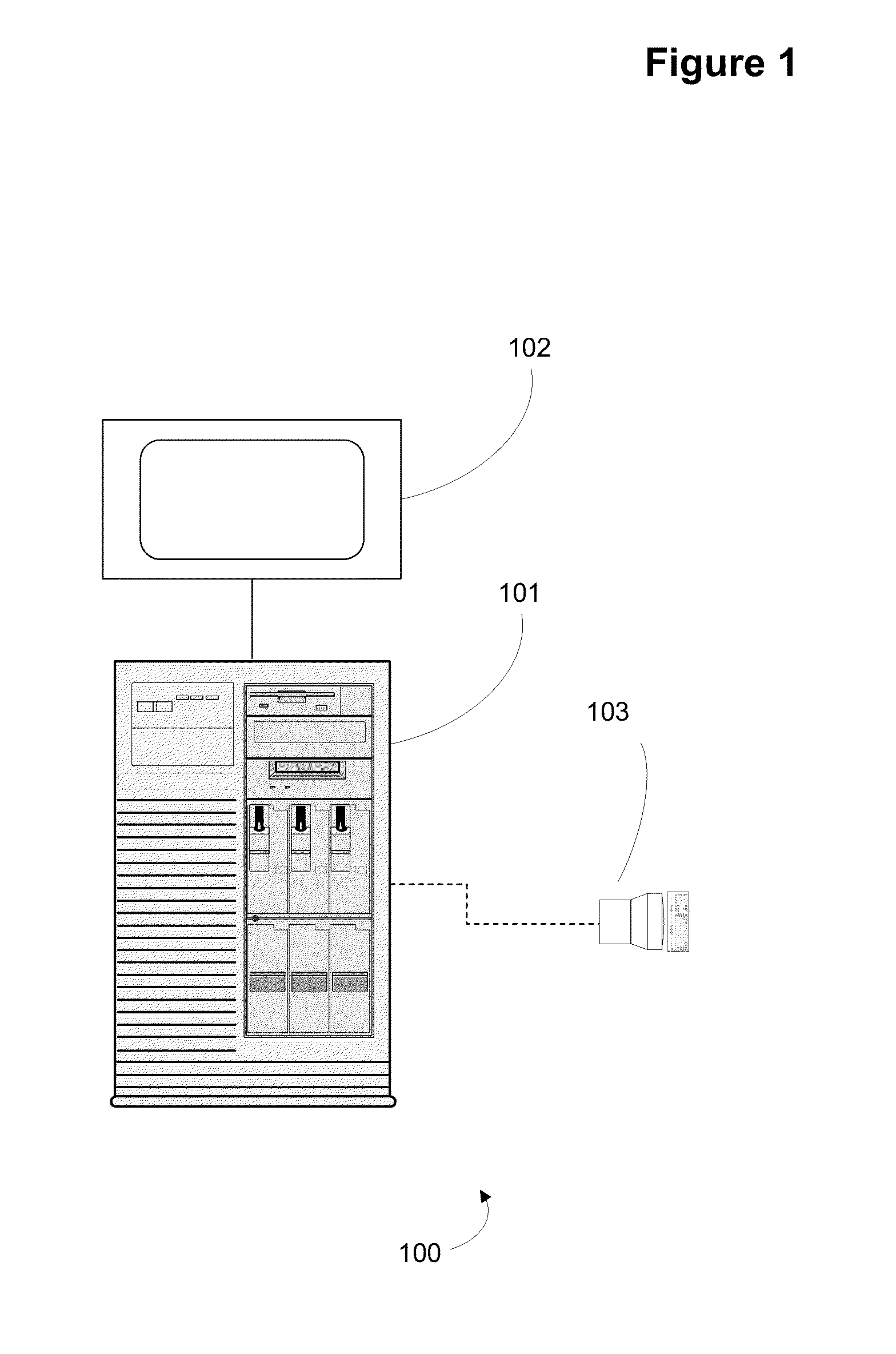
[0036]FIG. 1 is an architectural view of system 100. In this figure, computer 101 is coupled with associated display 102, eith...


PUM


Abstract

System and method for periodic body scan differencing for detecting changes in surface and subsurface body scans over time. May include use of a scanner and a computer system configured to scan a portion of body at first point in time to yield first scan, scan the portion of the body at second point in time to yield second scan, difference the two scans to produce a morphological difference image, and display the morphological difference image. May utilize surface or subsurface scans. Any type of scanner may be utilized that scans to the desired resolution of morphological testing. Can morph scan(s), geometrically, visually or both, to account for age, weight or color differences that have occurred between scans. Can display morphological surface or subsurface differences between scans in multiple images or atlas view. Differences can be displayed independently or overlaid onto scan(s). Differences may be highlighted to make more readily viewable.

Description

BACKGROUND OF THE INVENTION[0001]1. Field of the Invention[0002]Embodiments of the invention described herein pertain to the field of computer systems. More particularly, but not by way of limitation, one or more embodiments of the invention enable a system and method for periodic body scan differencing for detecting changes in surface and subsurface body scans over time.[0003]2. Description of the Related Art[0004]There are many types of methods for scanning a biological specimen, such as a body. Methods include introducing energy to a body and recording energy that transmits through a body or reflects back from a body. These methods are utilized for subsurface scanning and surface scanning. Generally, the methods are directed at diagnosing or investigating ailments or functions of a body. One type of scanning includes medical imaging. Medical imaging includes radiological, thermographic, photographic, microscopic and acoustic imaging. Within the medical imaging area, morphological...

Claims


Application Information

Patent Timeline
Patent Type & Authority Patents(United States)
IPC IPC(8): G06K9/00G09G5/00G06T15/00
CPCG06T2207/30196G06T7/2053G06T2207/30004G06T7/0016G06T7/254
Inventor PASSMORE, CHARLES, G.
Owner PASSMORE CHARLES G
Why Eureka
Try Eureka