Electronically-configurable key

a technology of electronic configuration and keys, applied in the field of keys, can solve the problems of high system is susceptible to illicit access, and complicated means, and achieve the effects of reducing the cost of smart locks, and reducing the complexity of means

Inactive Publication Date: 2014-02-11
LESSELS PETER J
View PDF31 Cites 10 Cited by
  • Summary
  • Abstract
  • Description
  • Claims
  • Application Information

AI Technical Summary

Benefits of technology

[0008]The smart key described herein overcomes the problem of carrying multiple keys that is currently required for systems which do not employ smart locks. The smart key is designed to operate with conventional axial pin locks, and can be programed to provide many of the advantages of a smart lock systems without requiring existing locks to be replaced with costly smart locks. The axial pin locks for which the smart keys of the present invention are designed to open have an indexing element and n lock pins, n typically being 7 or 8. The smart key herein described relies on having available information on the position of the lock pins for a particular lock to create a shear plane to place the lock in a condition for opening. This information is stored in a key database as well as an associated index based on a lock identifier associated with the lock. This identifier can be provided in a variety of formats, such as an alphanumeric character string, a bar code, or a RFID chip, all of which can be input to the smart key via a lock ID input interface.
[0016]When multiple axial positioning means are employed and provide a dedicated axial positioner for each drive pin, such a system can reduce the complexity of the means for positioning the n drive pins by eliminating the need to rotate (translate) an axial positioning means about the key axis. Since there is no rotary / translational motion of the axial positioning means, this scheme also allows coupling linkage between the motor or servo and the drive pins, and may eliminate the need for pin reset mechanism. While the spacing between the drive pins may not be sufficient to accommodate the number of individual axial positioning devices needed, the coupling linkages can each be configured to provide an offset to allow sufficient spacing to accommodate these devices while maintaining a smaller separation between the drive pins. The linkage can also be configured to provide a reduction in displacement, facilitating precise positioning of the associated drive pin.
[0017]Since the key has an on-board microprocessor, it is possible for the microprocessor to be programmed so that it can perform many of the functions provided by systems that employ smart locks, such as limiting access to particular locks based on time, limiting the number of times a lock can be accessed before requiring reauthorization, creating a history of locks opened with the particular key, etc.

Problems solved by technology

However, this system requires the user to carry a large number of keys, which can be unwieldy if a large number of locks are employed.
This problem is exacerbated for service technicians who may need to service machines belonging to more than one service route.
Furthermore, this system is susceptible to illicit access by a dishonest keyholder, such as employee theft.
While such systems provide security advantages, the costs of the smart locks are high.
This becomes a severe cost burden for uses where a large number of locks must be employed.
In the case of vending machine systems, the high cost of purchasing such smart locks is frequently prohibitive for the vendor who distributes goods through routes having a large number of vending machines.

Method used


Image

  • Electronically-configurable key
  • Electronically-configurable key
  • Electronically-configurable key

Examples


Embodiment Construction

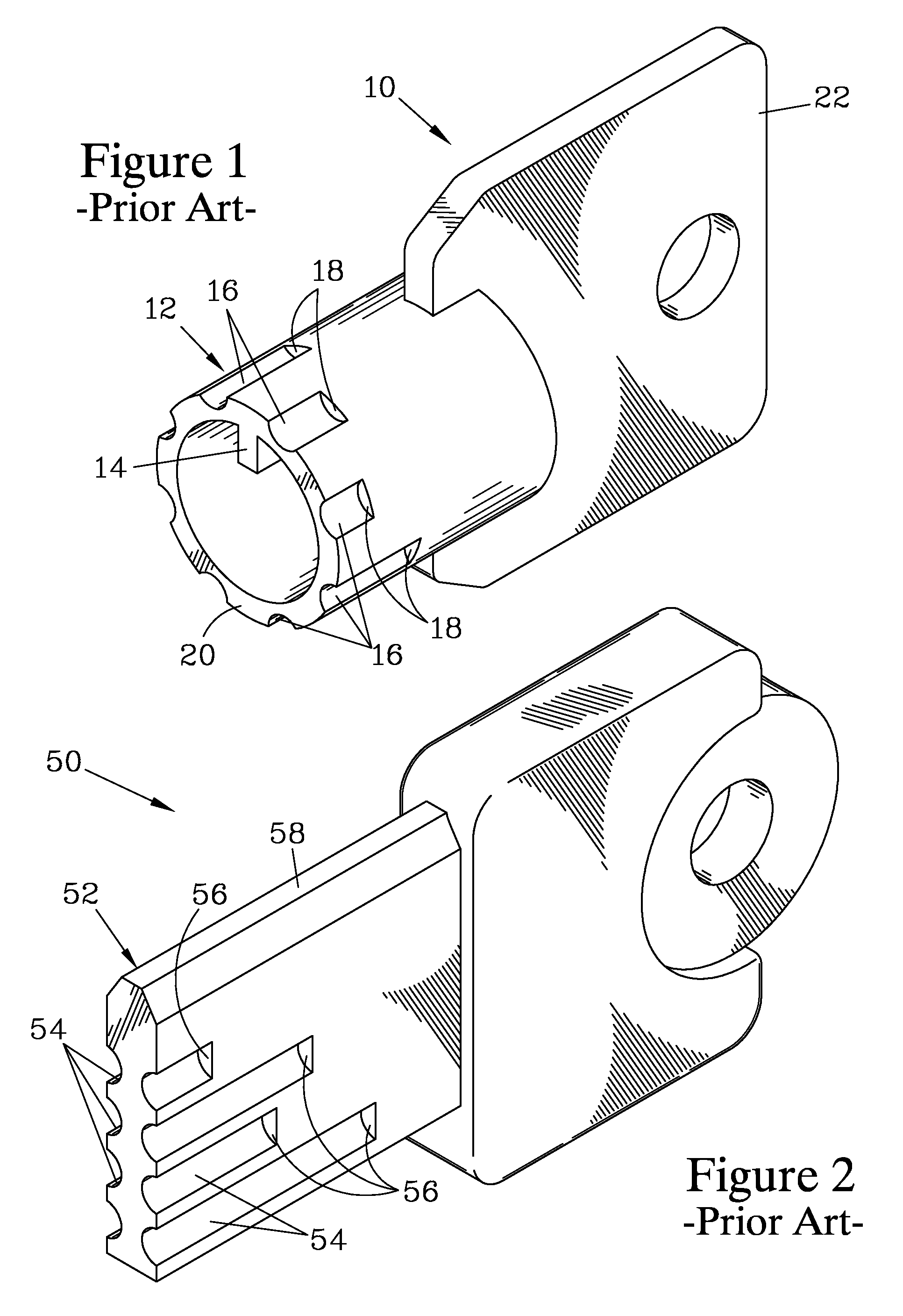
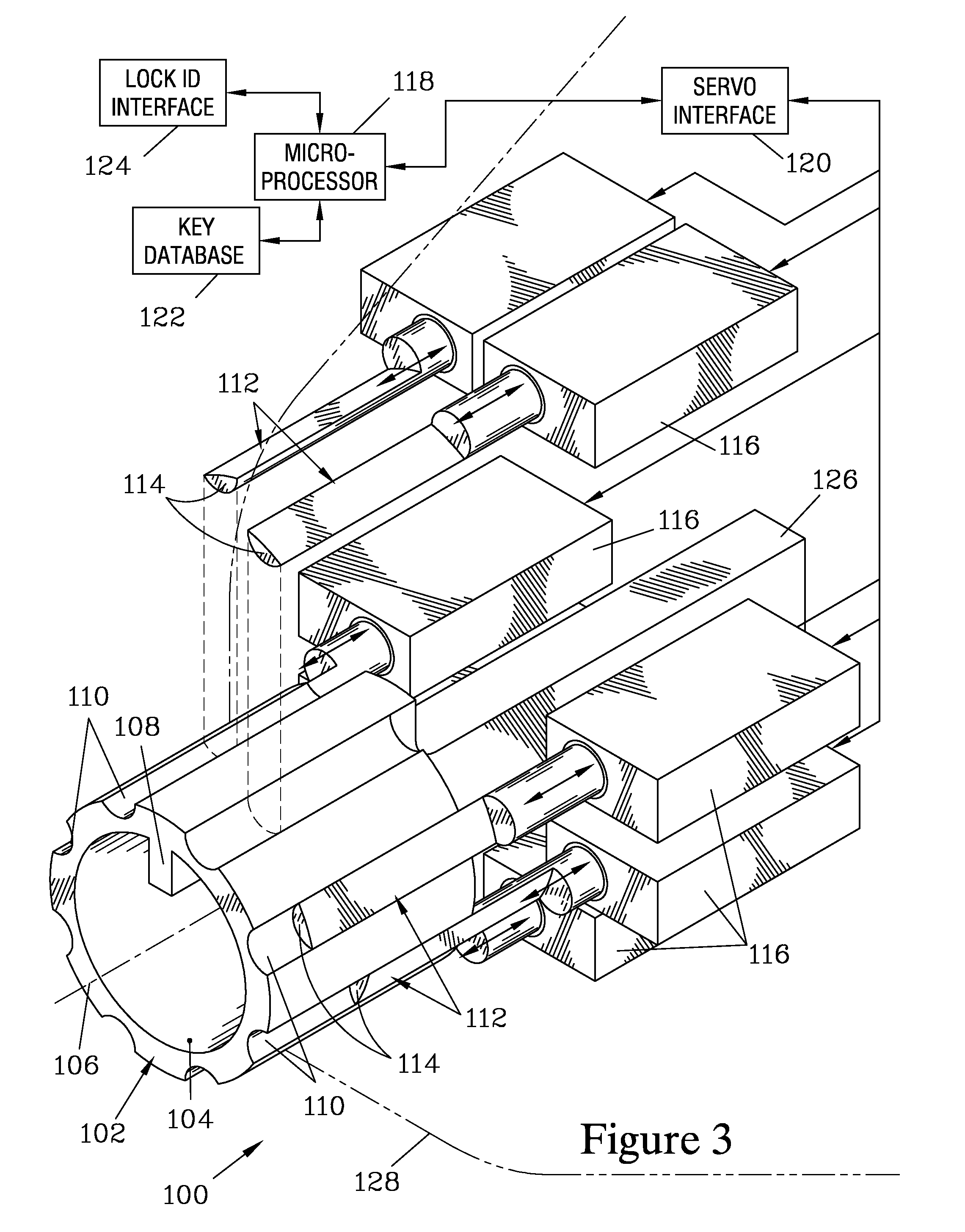
[0025]FIG. 3 is a partially-exploded isometric view of a key 100 that forms one embodiment of the present invention. The key 100 can be configured to provide the same function as the prior art key 10 discussed above and shown in FIG. 1, as well as being configured to match the configurations of other, similar keys in order to open other conventional locks without requiring modification or replacement of such locks. Allowing the key 100 to be re-configured to match the pin configuration of other locks allows a user to open a number of locked objects with a single key 100. The key 100 can, in some embodiments, optionally perform additional security features.

[0026]The key 100 has a base member 102 that is substantially cylindrical, defining an open central region 104, both the base member 102 and the central region 104 being symmetrically disposed about a central axis 106. The base member 102 has an indexing tab 108 that, in this embodiment, extends into the central region 104 and is c...


PUM


Abstract

A key for opening multiple axial pin locks has a base member with an indexing element and a number of lock pins, configured to match the keyways of the locks. The key has a microprocessor with access to information on the pin configuration for each lock to be opened, and the lock pins are selectively positioned along the base member to match the configuration of a key for a particular lock in response to the user entering an identification code for that lock. The lock pins can slidably engage recessed tracks in the base member, which serve to direct the lock pins parallel to an axis of the base member. A pin latching mechanism can be provided to secure the lock pins in the desired position.

Description

FIELD OF THE INVENTION[0001]The present invention relates to keys employed with axial pin locks, and more particularly to a single key that can be selectively configured to open a number of such locks without requiring such locks to be modified.BACKGROUND OF THE INVENTION[0002]Axial pin locks are frequently employed to secure objects such as vending machines to prevent unauthorized access. An axial pin lock provides a simple mechanical lock for securing each machine, resulting in a series of locks for a route of machines; the route attendant servicing the machines is provided with a matching series of keys.[0003]FIG. 1 illustrates one example of a prior art key 10 for opening a tubular axial pin lock (not shown) to obtain access to a locked storage container such as a vending machine to be serviced to collect money and replenish the items to be sold. Examples of such locks where the lock pins are arranged in a circular pattern are taught in U.S. Pat. Nos. 4,716,749 and 5,018,376. Th...

Claims


Application Information

Patent Timeline
Patent Type & Authority Patents(United States)
IPC IPC(8): E05B25/00
CPCE05B19/0047G07C9/00944E05B47/00E05B19/18E05B19/0088G07C9/00857Y10T70/7819Y10T70/7734Y10T70/625Y10T70/7881Y10T70/7073Y10T70/7525Y10T70/7893Y10T70/7051Y10T70/7079Y10T70/7621Y10T70/7791Y10T70/7593Y10T70/7605
Inventor LESSELS, PETER, J.
Owner LESSELS PETER J
Why Eureka
Try Eureka