Securing member

a technology of fixing member and fixing member, which is applied in the direction of branching pipes, solar thermal energy generation, solar heating energy, etc., can solve the problems of troublesome installation operation and increased cost, and achieve the effect of enhancing the installation strength of solar battery module on the roof til

Active Publication Date: 2014-02-11
YANEGIJUTSUKENKYUJO CO LTD
View PDF20 Cites 35 Cited by
  • Summary
  • Abstract
  • Description
  • Claims
  • Application Information

AI Technical Summary

Benefits of technology

[0010]In addition, on the securing member 200, a cover member 220 is mounted so as to cover an upper surface of the securing member 200. A hole portion 221 through which the shaft portion 203B of the bolt is inserted is punctured on the cover member 220. The cover member 220 is mounted for limiting a range where the bolt 203 can slide in order to prevent the bolt 203 sliding in the groove 202 from being detached from the groove 202 having an opening end. With this configuration, there has arisen a problem that the number of parts is increased so that an installation operation is troublesome and cost is increased.
[0011]In view of the above circumstances, an object of the present invention is to provide a securing member having the reduced number of parts, which can secure a solar battery module onto roof tile at an appropriate position, and can be generally used for a common solar battery module.
[0016]With the above configuration, the base portion is mounted on the roof tile, the shaft portion of the bolt with the inverted head in a state where the shaft portion is inserted through the long hole portion is further inserted through the supporting hole portion of the supporting member, and then, is fastened with a nut. With this, the supporting member can be secured onto the roof tile through the securing member. Eventually, the solar battery module supported by the supporting member can be secured onto the roof tile. At this time, the bolt can be made to slide along the long hole portion. Therefore, the base portion and the supporting member can be made to slide relatively. In other words, the base portion and the supporting member can be separated from or made closer to each other by a length of the long hole portion. With this, the solar battery module can be supported by the supporting member in a balanced manner in a state where the securing member is mounted on the roof tile at an appropriate position.
[0017]Note that the securing hole portion is punctured on the base portion. Therefore, the securing member can be mounted on the roof tile by a fastener member such as a nail or a screw nail, which is inserted through the securing hole portion. In the aspect of the invention, the securing hole portion “is located on a line obtained by projecting a center axis line of the long hole portion on the base portion.” That is, the securing hole portion is located on a virtual line just under a center axis line of the long hole portion. Therefore, the securing member is attached to the roof tile on the same axis as a portion on which the securing member receives load supported by the supporting member through the bolt. Therefore, the solar battery module can be secured onto the roof tile through the securing member stably. In particular, if the securing hole portion is adjusted to be located on a structural material such as rafter, the securing member is supported by the structural member stably and installation strength of the solar battery module on the roof tile through the securing member and the supporting member can be enhanced and it is preferable.
[0021]In addition to attachment of the securing member to the roof tile by the fastener member inserted through the securing hole portion as described above, the securing member can be also attached to the roof tile by the fastener members inserted through the “auxiliary securing hole portions.” Accordingly, the securing member can be secured onto the roof tile more firmly. Eventually, an installation strength of the solar battery module on the roof tile can be enhanced.
[0022]Note that the “base side edge portions” on which the auxiliary securing hole portions are provided are portions at outer sides with respect to the top board supporting portions and are not covered by the top board portion. Therefore, rainwater flows down the base side edge portions due to rainfall. At this time, the rainwater tends to flow into the groove portions formed along the boundaries between the base side edge portions and the top board supporting portions. This makes it possible to further decrease a risk that the rainwater enters through the auxiliary securing hole portions. It is to be noted that waterproof processing can be performed on the auxiliary securing hole portions into which the fastener members have been inserted by filling the auxiliary securing hole portions with calking agents.

Problems solved by technology

With this configuration, there has arisen a problem that the number of parts is increased so that an installation operation is troublesome and cost is increased.

Method used


Image

  • Securing member
  • Securing member
  • Securing member

Examples


Embodiment Construction

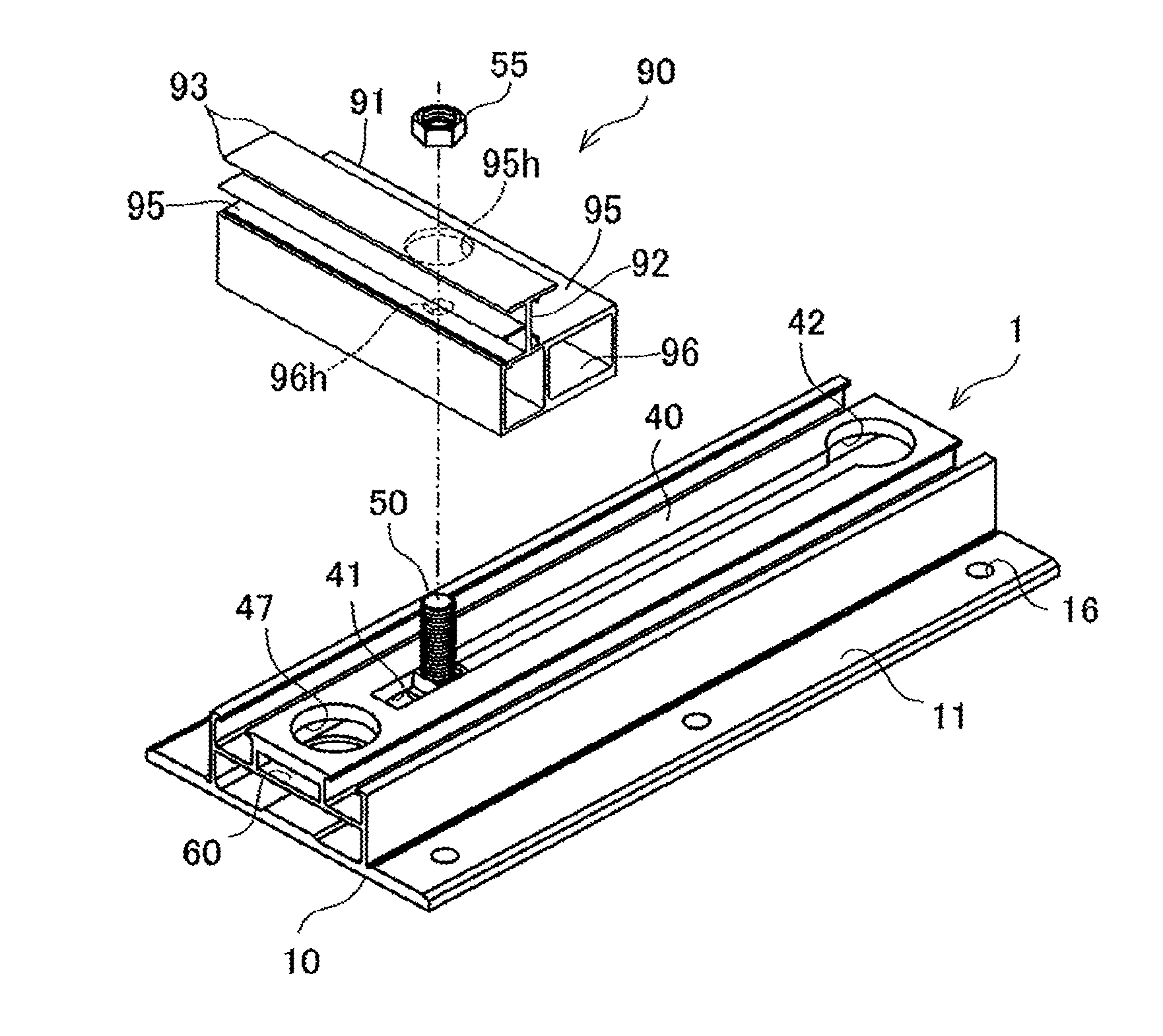
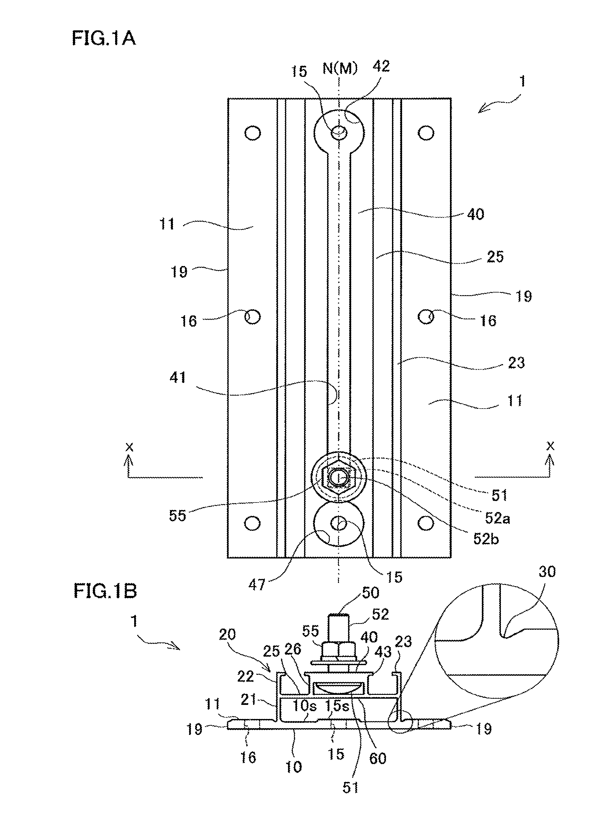
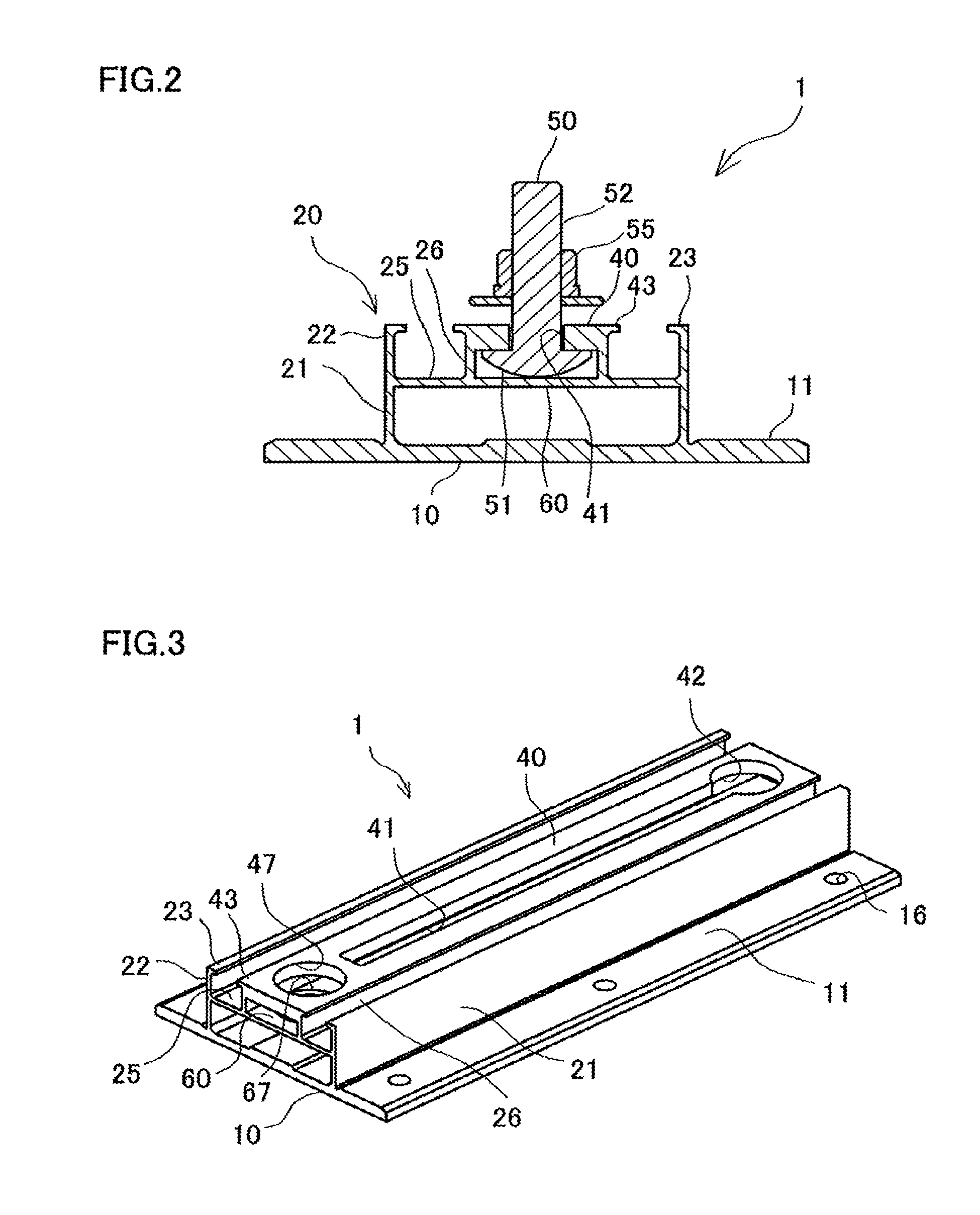
[0043]Hereinafter, a securing member 1 as a first embodiment of the invention is described with reference to FIG. 1A to FIG. 7.

[0044]The securing member 1 includes a flat plate-like base portion 10, a flat plate-like top board portion 40, a long hole portion 41, a bolt 50, a head insertion hole 42, and securing hole portions 15. The base portion 10 is to be mounted on roof tile. The top board portion 40 is supported at a position higher than the base portion 10 by a pair of top board supporting portions 20 erected on the base portion 10. The long hole portion 41 penetrates through the top board portion 40 and both ends of the long hole portion 41 are closed. The bolt 50 includes a shaft portion 52 which has such a size that the shaft portion 52 passes through the long hole portion 41 and a head 51 which has such a size that the head 51 does not pass through the long hole portion 41. The shaft portion 52 of the bolt 50 is inserted through the long hole portion 41 in a state where the...


PUM


Abstract

A securing member includes a flat base portion, a flat top board portion which is supported by a pair of top board supporting portions erected on the base portion, a long hole which penetrates through the top board portion and of which both ends are closed, a bolt having a head which does not pass through the long hole, and of which shaft is inserted through the long hole in a state where the head is located lower than the top board portion and is to be inserted through a supporting hole provided on a supporting member of a solar battery module, a head insertion hole through which the head of the bolt passes, penetrates through the top board portion, and communicates with the long hole, securing holes which are located on a line obtained by projecting a center line of the long hole, and penetrate through the base portion.

Description

[0001]This application is a continuation of International Application No. PCT / JP2010 / 066180 filed on Sep. 17, 2010 claiming priority upon Japanese Patent Application No. 2010-021476 filed Feb. 2, 2010, of which full contents are incorporated herein by reference.BACKGROUND OF THE INVENTION[0002]1. Field of the Invention[0003]The present invention relates to a securing member which is used for securing a member which supports a solar battery module onto roof tile when the solar battery module is installed on roof.[0004]2. Description of the Related Art[0005]When a solar battery module is installed on roof of a building, long crosspieces are mounted on roof tile so as to be assembled in a form of parallel crosses and the solar battery module is secured onto the roof tile through the crosspieces, in general. With this, there is an advantage that spaces between the crosspieces can be adjusted in accordance with a size of the solar battery module by adjusting intersecting positions of the...

Claims


Application Information

Patent Timeline
Patent Type & Authority Patents(United States)
IPC IPC(8): F16B7/04
CPCF24J2/526F24J2/5245F24J2/5205F24J2/5258Y02E10/47Y02B10/20Y02B10/12Y10T403/142Y10T403/33Y10T403/4662F24S25/61F24S25/33F24S25/65F24S25/636F16B2200/20Y02E10/50Y02B10/10H02S20/23E04D13/00
Inventor KOBAYASHI, SHUICHI
Owner YANEGIJUTSUKENKYUJO CO LTD
Why Eureka
Try Eureka