
Polishing pad, and method for manufacturing polishing pad

a technology of polishing pad and polishing surface, which is applied in the direction of gear teeth, grinding devices, manufacturing apparatus of gear teeth, etc., can solve the problems of uneven polishing rate, uneven surface, and increased scratching or interfacial separation of polishing surface, etc., and achieve excellent flattening performance and resistance to scratching

Active Publication Date: 2014-02-11
KURARAY CO LTD
View PDF43 Cites 10 Cited by
  • Summary
  • Abstract
  • Description
  • Claims
  • Application Information

AI Technical Summary

Benefits of technology

[0028]It is an object of the present invention to provide a polishing pad that is resistant to scratching and also has excellent flattening performance.

Problems solved by technology

However, if agglomerated abrasive grains are present on the polishing surface, the load will also be selectively applied to these agglomerated grains, making the polishing surface more susceptible to scratching.
In particular, as described in Non-Patent Document 1, when a substrate having copper wiring that is easily scratched, or a material with a low dielectric constant and low interfacial adhesive strength is polished, scratching or interfacial separation is especially apt to occur.
Also, in a cast-foam-molding, it is difficult to foam a macromolecular elastomer uniformly, which means that there tends to cause variance in the flatness of the substrate being polished and in the polishing rate during polishing.
Furthermore, with a polishing pad having independent pores, the voids originating in the independent pores can become clogged with abrasive grit and polishing dust.
However, because the nonwoven cloth polishing pads are flexible, the polishing rate is low.
Also, because the polishing pad deforms by conforming to the surface shape of the substrate being polished, high flattening performance (the characteristic of making the polished substrate flat) is not obtained.

Method used

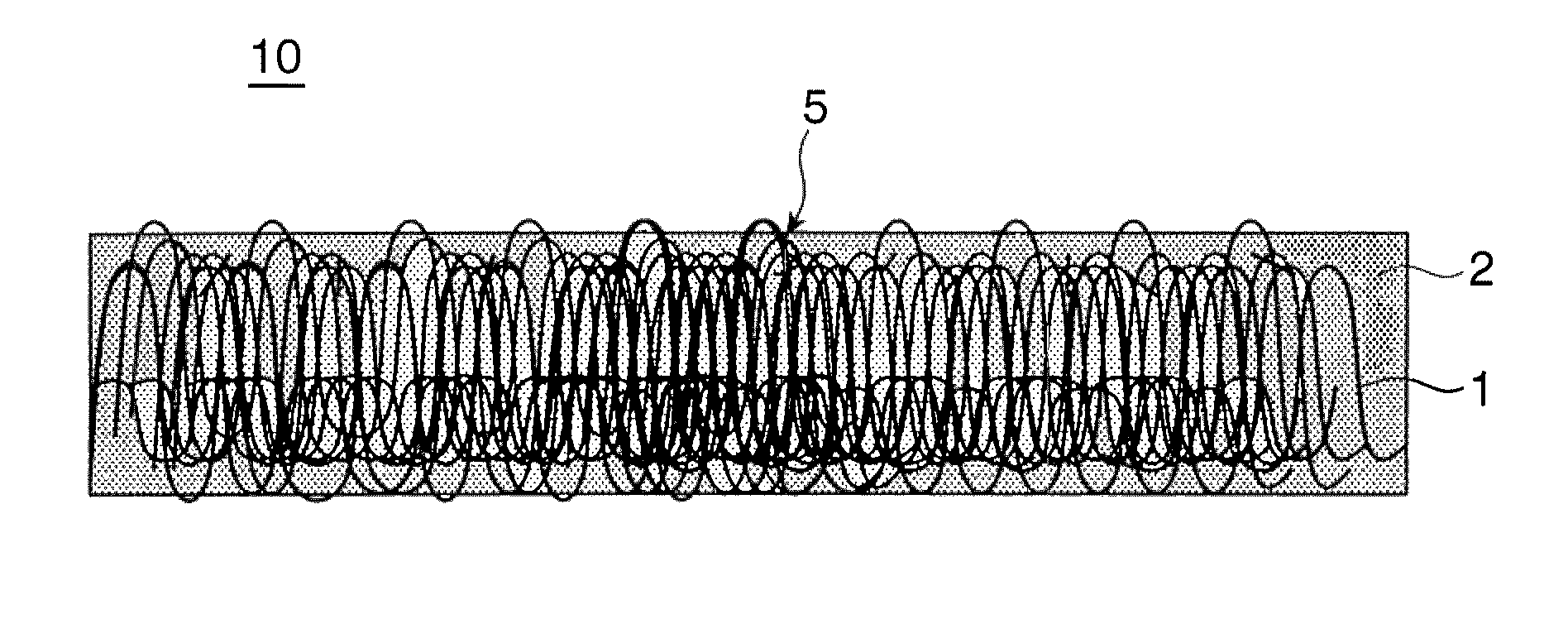
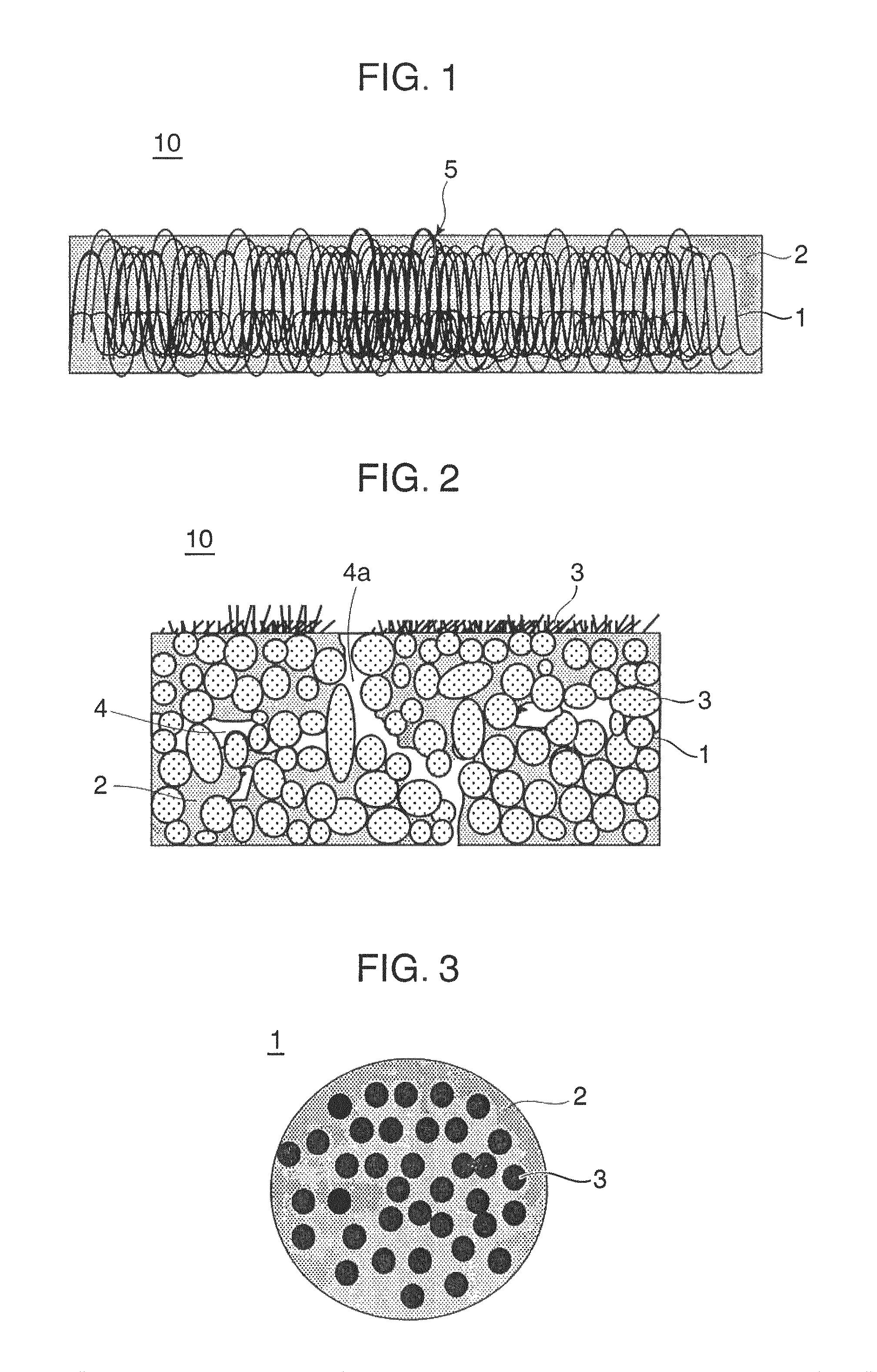
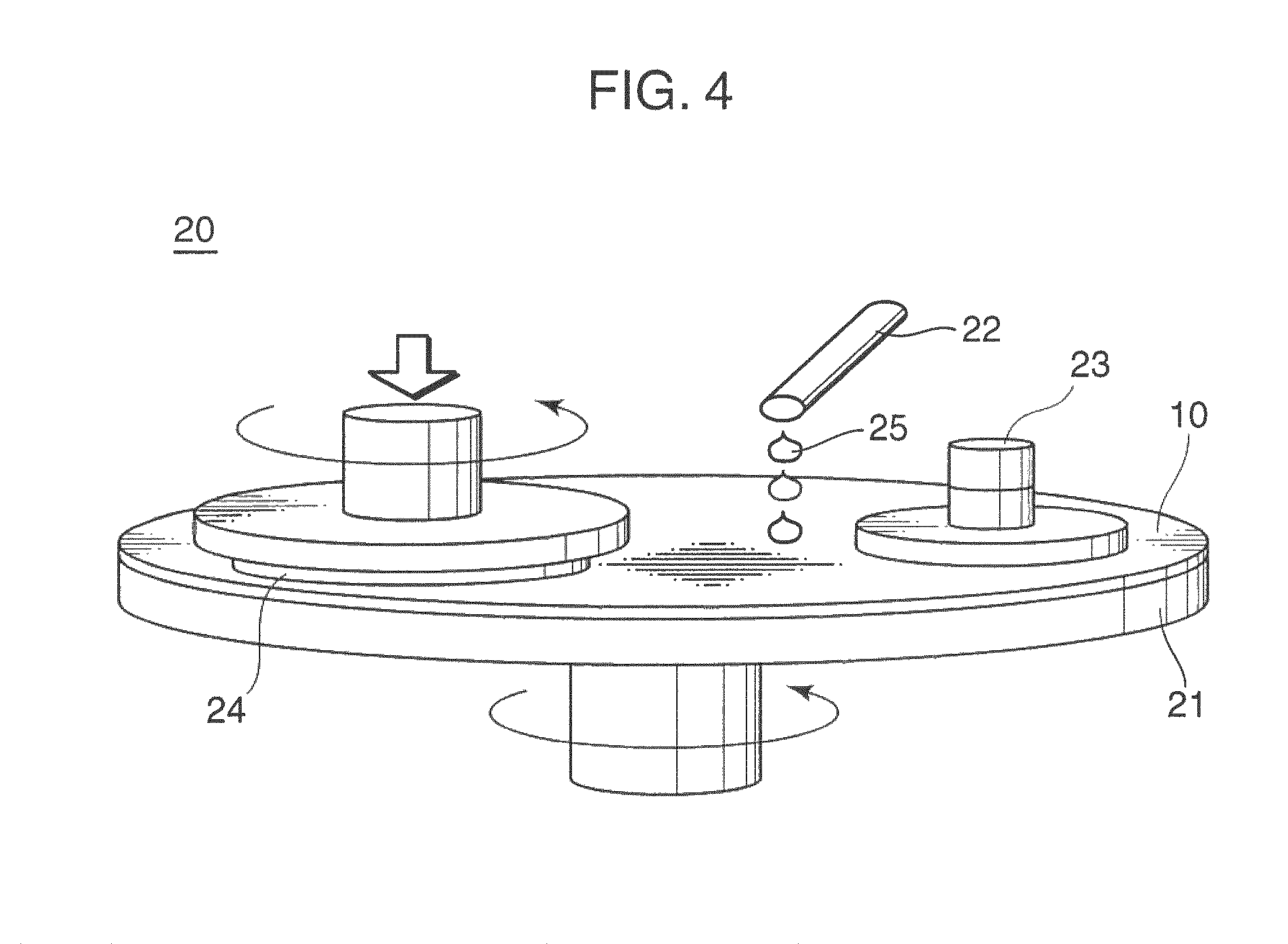

Image

  • Polishing pad, and method for manufacturing polishing pad
  • Polishing pad, and method for manufacturing polishing pad
  • Polishing pad, and method for manufacturing polishing pad

Examples


working examples

Working Example 1

[0188]An islands-in-the-sea composite fiber was formed by discharging a water-soluble thermoplastic polyvinyl alcohol resin (hereinafter referred to as PVA resin) and isophthalic acid-modified polyethylene terephthalate with a degree of modification of 6 mol % (hereinafter referred to as modified PET; Tg of 77° C., water absorbency of 1 mass, nominal water content of 0.4 mass %) in a ratio of 20:80 (mass ratio) from a composite melt spinning nozzle. The composite melt spinning nozzle had 25 islands per fiber and a nozzle temperature of 260° C. The ejector pressure was adjusted to achieve a spinning rate of 4000 m / min, and long fibers with an average size of 2.0 dtex were caught in a net to obtain a spun-bond sheet (long fiber web) with a basis weight of 30 g / m2.

[0189]16 sheets of the spun-bond sheets thus obtained were cross-lapped to produce a lapped web with a total basis weight of 480 g / m2. The lapped web thus obtained was sprayed with an oil to prevent needle br...

working example 2

[0196]An islands-in-the-sea composite fiber was formed by discharging the PVA resin and the modified PET in a ratio of 25:75 (mass ratio) from a composite melt spinning nozzle. The composite melt spinning nozzle had 25 islands per fiber and a nozzle temperature of 260° C. The ejector pressure was adjusted to achieve a spinning rate of 4000 m / min, and long fibers with an average size of 2.0 dtex were caught in a net to obtain a spun-bond sheet (long fiber web) with a basis weight of 30 g / m2.

[0197]18 sheets of the spun-bond sheets thus obtained were cross-lapped to produce a lapped web with a total basis weight of 540 g / m2. The stacked web thus obtained was sprayed with an oil to prevent needle breakage. Then, the stacked web was entangled by needle punching at 1800 punches / cm2 using a No. 42 needle with one barb and a No. 42 needle with six barbs, which gave a web entangled sheet. The resulting web entangled sheet had a basis weight of 830 g / m2 and an interlayer separation strength o...

working example 3

[0203]An islands-in-the-sea composite fiber was formed by discharging the PVA resin and the modified PET in a ratio of 20:80 (mass ratio) from a composite melt spinning nozzle. The composite melt spinning nozzle had 25 islands per fiber and a nozzle temperature of 260° C. The ejector pressure was adjusted to achieve a spinning rate of 4000 m / min, and long fibers with an average size of 2.0 dtex were caught in a net to obtain a spun-bond sheet (long fiber web) with a basis weight of 30 g / m2.

[0204]18 sheets of the spun-bond sheets thus obtained were cross-lapped to produce a lapped web with a total basis weight of 540 g / m2. The lapped web thus obtained was sprayed with an oil to prevent needle breakage. Then, the lapped web was entangled by needle punching at 2000 punches / cm2 using a No. 42 needle with one barb and a No. 42 needle with six barbs, which gave a web entangled sheet. The resulting web entangled sheet had a basis weight of 870 g / m2 and an interlayer separation strength of ...


PUM

PropertyMeasurementUnit
areaaaaaaaaaaa
areaaaaaaaaaaa
cross sectional areaaaaaaaaaaa

Abstract

It is an object of the present invention to provide a polishing pad that is resistant to scratching and also has excellent flattening performance. One aspect of the present invention is a polishing pad, comprising a fiber-entangled body formed from fiber bundles made up of ultrafine fibers in which the average cross sectional area is between 0.01 and 30 μm2, and a macromolecular elastomer, wherein part of the macromolecular elastomer is present inside the fiber bundles, whereby the ultrafine fibers are bundled, the number of fiber bundles per unit of surface area present in a cross section in the thickness direction is at least 600 bundles per square millimeter, and the volumetric ratio of a portion excluding voids is between 55 and 95%.

Description

TECHNICAL FIELD[0001]This invention relates to a polishing pad, and more particularly relates to a polishing pad that is used to polish semiconductor wafers, semiconductor devices, silicon wafers, hard disks, glass substrates, optical products, various metals, and the like, and to a method for manufacturing this pad.BACKGROUND ART[0002]As integrated circuits have increased in integration and evolved into multilayer wiring in recent years, the semiconductor wafers on which these integrated circuits are formed need to be flat to a high degree of precision.[0003]Chemical-mechanical polishing (CMP) is a known polishing method for polishing semiconductor wafers. CMP involves polishing the surface of a substrate to be polished with a polishing pad while a slurry of abrasive grains is dropped onto the surface.[0004]The following Patent Documents 1 to 4 disclose polishing pads used in CMP, which are composed of a polymer foam having an independent cell structure and being manufactured by fo...

Claims


Application Information

Patent Timeline
Patent Type & Authority Patents(United States)
IPC IPC(8): B24B37/24B24D11/00
CPCB24B37/24B24D18/00B24D3/32B24D3/26B24D11/00H01L21/304
Inventor NAKAYAMA, KIMIOTAKAOKA, NOBUOKATO, MITSURUKIKUCHI, HIROFUMITANAKA, JIRO
Owner KURARAY CO LTD
Learn More