Hydrogen energy systems

a technology of hydrogen energy and hydrogen gas, applied in electrochemical generators, transportation and packaging, packaging goods types, etc., can solve the problems of difficult impracticality of storage, and difficulty in safe storage of hydrogen gas for system energy supply, so as to increase fuel demand and increase fuel demand

Active Publication Date: 2014-02-18
SMITH PAUL H JR
View PDF16 Cites 14 Cited by
  • Summary
  • Abstract
  • Description
  • Claims
  • Application Information

AI Technical Summary

Benefits of technology

[0005]It is a further object and feature of the present invention to provide such a hydrogen energy system wherein such magnesium hydride may be safely stored.
[0009]Yet another object and feature of the present invention is to provide controlled coherent light energy to successive portions of a surface of such magnesium hydride disk to provide controlled release of hydrogen gas.
[0012]Another primary object and feature of the present invention is to provide a system of manufacturing magnesium hydride disks, which disks may releasably store hydrogen within a compact volume.
[0015]In accordance with a preferred embodiment hereof, this invention provides a process, relating to controlled commercial use of hydrogen gas, comprising the steps of: providing at least one supply of hydrogen gas; and providing at least one electromagnetic field sufficient to form at least one supply of hydrogen plasma; wherein such at least one supply of hydrogen plasma is formed adjacent to at least one metal surface portion capable of storing hydrogen; and wherein such at least one metal surface portion absorbs hydrogen from such at least one supply of hydrogen plasma to form at least one metal hydride; and providing at least one hydrogen storer structured and arranged to store, using such at least one metal hydride, at least one substantial amount of hydrogen so as to permit photonic-excitation-assisted release of stored hydrogen; using at least one photonic exciter to photonically excite such at least one hydrogen storer to assist release of such stored hydrogen as hydrogen gas; and controlling such photonic-excitation-assisted release of such hydrogen gas so as to assist at least one commercial use.

Problems solved by technology

In using hydrogen energy systems, it is difficult to safely store hydrogen gas for use in providing energy for systems, such as vehicles, given the highly combustible nature of hydrogen.
While hydrogen has a high energy to weight ratio, storage of hydrogen in a gaseous state (even compressed) yields a low energy to volume ratio making such storage impractical, particularly for mobile use.

Method used


Image

  • Hydrogen energy systems
  • Hydrogen energy systems
  • Hydrogen energy systems

Examples


embodiment 101

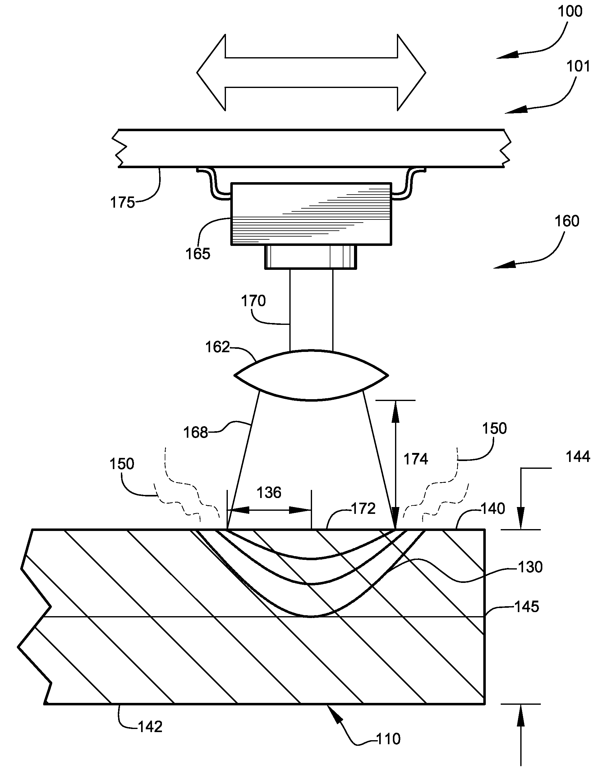
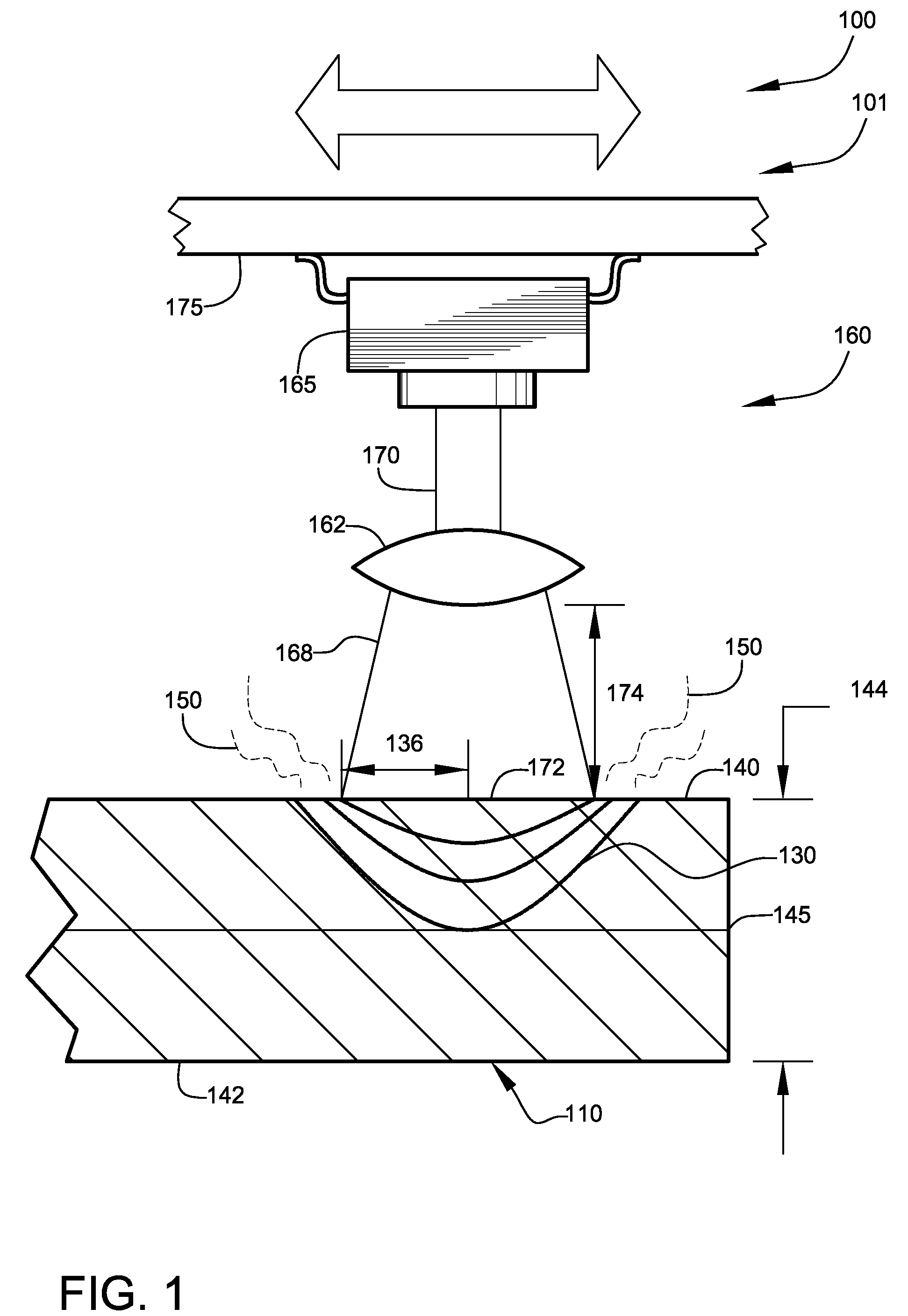
[0072]FIG. 1 shows a partial side view of at least one hydride disk 110, illustrating release of hydrogen gas 150 preferably by laser heating, according to a preferred embodiment of the present invention. Hydrogen energy system 100 preferably comprises embodiment 101, as shown. Hydride disk 110 preferably comprises at least one metal hydride, preferably substantially magnesium hydride. As discussed herein, concentration of hydrogen, stored in hydride disk 110, preferably should be greater than about 5% by weight, for economical efficiency. Magnesium hydride theoretically maximally stores about 7.6% hydrogen by weight. Upon reading this specification, those skilled in the art will now appreciate that, under appropriate circumstances, considering such things as then available forms of metal hydride, abilities to place such forms in a rotatable “disk” shape structure for use with controlled laser heating, etc., other “disks” than unitary and / or complete “disks”, such segmented, liquid,...

embodiment 1200

[0137]FIG. 14 shows a diagrammatic view, illustrating the atomic order of hydride disk 1210, according to embodiment 1200 of FIG. 13. Hydride disk 1210 preferably comprises multiple layers 1265 of hydrogen-storing material 1270, preferably magnesium 1272, as shown. Hydrogen-storing material 1270 preferably comprises at least one crystalline structure 1275, as shown. Within crystalline structure 1275, hydrogen-storing material 1270 preferably stores hydrogen 1280, as shown.

[0138]FIG. 15 shows a flow chart, illustrating at least one hydride disk manufacturing process 1500, according to the preferred embodiment of FIG. 14. Hydride disk manufacturing process 1500 preferably comprises the steps of: precipitating sheet 1510; cutting disks 1520; perforating disks 1530; etching disks 1540; washing disks 1550; embedding catalysts 1560; and coating disks 1570. During hydride disk manufacturing process 1500, materials used and processes conducted are preferably kept in an inert atmosphere, alt...


PUM

PropertyMeasurementUnit
angleaaaaaaaaaa
diameteraaaaaaaaaa
wavelengthaaaaaaaaaa

Abstract

Hydrogen energy systems for obtaining hydrogen gas from a solid storage medium using controlled laser beams. Also disclosed are systems for charging / recharging magnesium with hydrogen to obtain magnesium hydride. Other relatively safe systems assisting storage, transport and use (as in vehicles) of such solid storage mediums are disclosed.

Description

CROSS-REFERENCE TO RELATED APPLICATIONS[0001]The present application is a continuation-in-part and is related to and claims priority from non-provisional patent application Ser. No. 12 / 212,571, filed Sep. 17, 2008, entitled “HYDROGEN ENERGY SYSTEMS”, which claims priority to related prior provisional application Ser. No. 60 / 973,369, filed Sep. 18, 2007, entitled “HYDROGEN ENERGY SYSTEMS”, prior provisional application Ser. No. 61 / 022,572, filed Jan. 22, 2008, entitled “HYDROGEN ENERGY SYSTEMS”, and prior provisional application Ser. No. 61 / 024,856, filed Jan. 30, 2008, entitled “HYDROGEN ENERGY SYSTEMS”; and is also related to International Patent Application No. PCT / US2008 / 076900, filed Sep. 18, 2008, entitled “HYDROGEN ENERGY SYSTEMS”; and also is related to and claims priority from prior provisional application Ser. No. 61 / 160,608, filed Mar. 16, 2009, entitled “HYDROGEN ENERGY SYSTEMS”; and further is related to and claims priority from prior provisional application Ser. No. 61 / ...

Claims


Application Information

Patent Timeline
Patent Type & Authority Patents(United States)
IPC IPC(8): C01B3/00B44C1/22B65D85/00C01B6/24C01B3/02
CPCY02E60/50H01M8/04201Y02E60/364Y02E60/327H01M8/04216H01M8/065C01B3/0026C01B6/00C01B3/0084C01B3/04Y02E60/32Y02E60/36
Inventor SMITH, JR., PAUL, H.
Owner SMITH PAUL H JR
Why Eureka
Try Eureka