Liquid droplet ejecting head and image forming apparatus

a technology of image forming apparatus and liquid droplet, which is applied in printing and other directions, can solve the problems of not being able to obtain high-definition image output, and achieve the effects of preventing mutual interference, superior damping function, and small siz

Active Publication Date: 2014-02-18
RICOH KK
View PDF13 Cites 0 Cited by
  • Summary
  • Abstract
  • Description
  • Claims
  • Application Information

AI Technical Summary

Benefits of technology

[0016]Thus, in view of the problems as described above, an object of the present invention is to provide a liquid droplet ejecting head which includes a superior damping function of preventing mutual interference caused through a common liquid chamber and which can be realized in a small size and at a low cost.
[0017]According to an embodiment of the present invention, a liquid droplet ejecting head is provided, including: at least one or more nozzles which eject liquid droplets; one or more dedicated liquid chambers which are communicatively connected to the nozzle; a common liquid chamber which is communicatively connected to the dedicated liquid chamber; and an energy generating unit which generates energy provided to the dedicated liquid chamber, wherein at least one wall face of the common liquid chamber includes a flexible wall, which has flexibility; a buffer chamber is included in an opposing area via the flexible wall and the common liquid chamber; and wherein the buffer chamber is communicatively connected to an external space in an area not opposing the common liquid chamber.
[0018]The liquid droplet ejecting head according to the present invention makes it possible to provide a liquid droplet ejecting head which includes a superior damping function of preventing mutual interference caused through a common liquid chamber and which can be realized in a small size and at a low cost.

Problems solved by technology

There is a problem that the mutual interference induces unintended ejecting of liquid droplets or destabilizing of an ejection state, resulting in not being able to obtain a high definition image output.

Method used


Image

  • Liquid droplet ejecting head and image forming apparatus
  • Liquid droplet ejecting head and image forming apparatus
  • Liquid droplet ejecting head and image forming apparatus

Examples


first embodiment

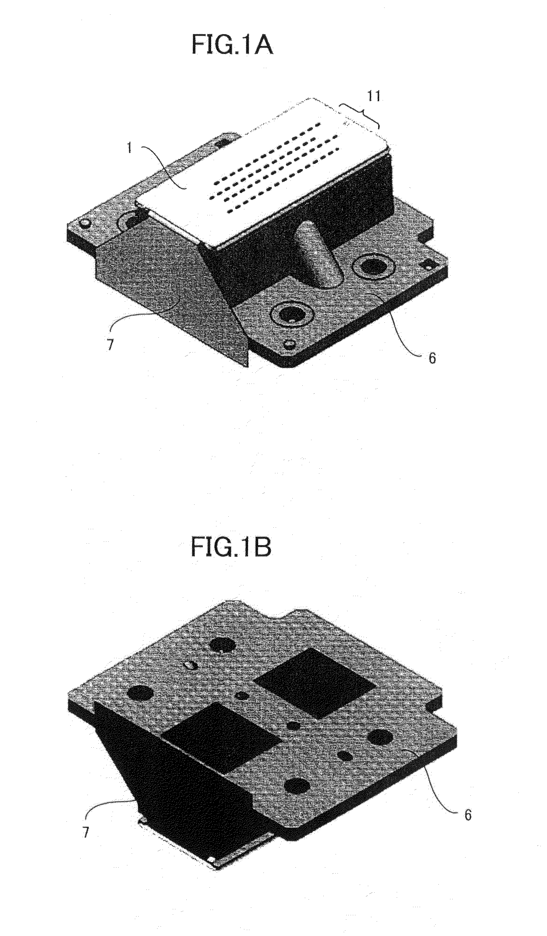
[0028]FIG. 1A is a perspective view showing an external view of one embodiment of a liquid droplet ejecting head according to the present invention, while FIG. 1B is a perspective view showing the external view of the opposite face of one embodiment of the liquid droplet ejecting head according to the present invention.

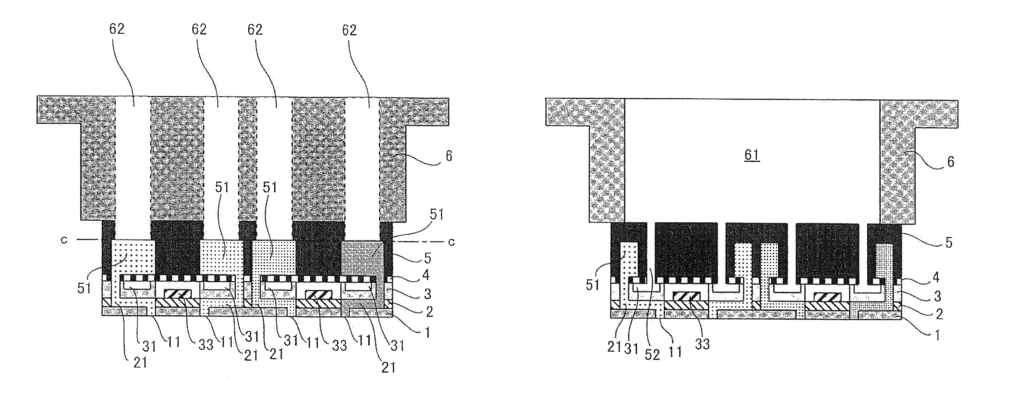
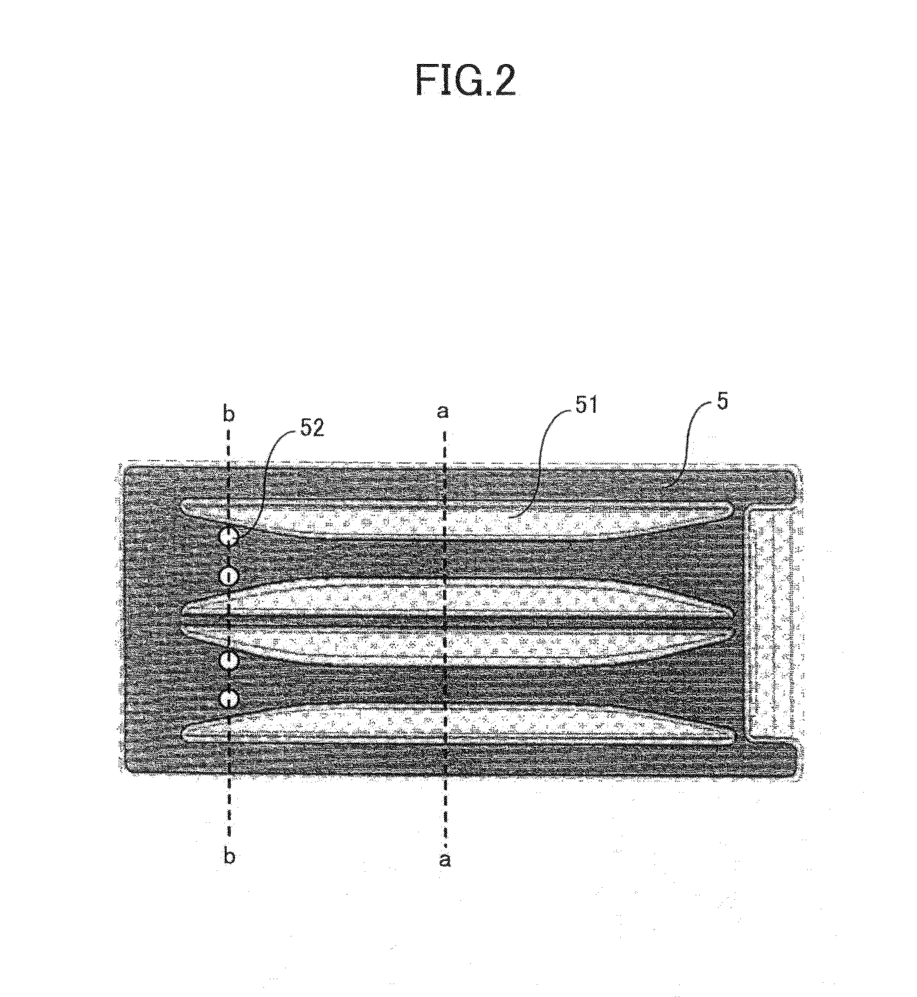
[0029]FIG. 2 is a plane view of a major portion of one embodiment of the liquid droplet ejecting head according to the present invention, while FIG. 3A is a sectional view thereof along a-a and FIG. 3B is a sectional view thereof along b-b. FIG. 2 is a sectional view of FIG. 3A along c-c.

[0030]As shown in FIGS. 3A and 3B, the liquid droplet ejecting head according to the present invention includes at least multiple nozzles 11 which eject liquid droplets; multiple dedicated liquid chambers (below called “pressure chambers”) which are communicatively connected to the nozzles; a common liquid chamber 51 which is communicatively connected to the dedicated liquid chambers;...

second embodiment

[0053]FIG. 4, which is a drawing illustrating a Second Embodiment of the liquid droplet ejecting head according to the present invention, is a sectional view along b-b of the area shown in FIG. 2.

[0054]As shown in FIG. 4, while the buffer chamber 31 is communicatively connected to the external space 61 through the communicatively connecting channel 52, the external space 61 which is communicatively connected thereto is a sealed space with a relatively large volume, not being open to the atmosphere.

[0055]When a resin film is used for the damper film 4, moisture in ink within the common liquid chamber 51 may evaporate through a moisture-permeating resin film, increasing an ink viscosity. When the ink viscosity increases, the ejecting characteristics change, possibly causing deterioration of an image quality. While it is preferable to seal the buffer chamber 31 in order to suppress an increase in the ink viscosity, the sealing of the buffer chamber exacerbates mutual interference cause...

third embodiment

[0057](A) in FIG. 5, illustrating a Third Embodiment of the liquid droplet ejecting head according to the present invention, is a sectional view along b-b of an area shown in FIG. 2. (B) in FIG. 5 is a plane view of an upper portion thereof.

[0058]According to the present embodiment, the buffer chamber is communicatively connected to the external space 61 through the communicatively connecting channel 52, while the external space 61 to which it is communicatively connected is communicatively connected to the atmosphere through a snake line 63.

[0059]The snake line 63 is formed as a groove cut on a top face of the housing 6, which groove having a length of 100 mm, and a cross section of a height of 300 μm and a width of 300 μm. It is formed by sealing this groove with a moisture permeation preventing film 8 (an aluminum sheet, for example).

[0060]Such a configuration makes it possible to prevent ink within the common liquid chamber 51 from evaporating and to ignore altogether the compre...


PUM


Abstract

A liquid droplet ejecting head is disclosed which includes at least one or more nozzles which eject liquid droplets; one or more dedicated liquid chambers which are communicatively connected to the nozzle; a common liquid chamber which is communicatively connected to the dedicated liquid chamber; and an energy generating unit which generates energy provided to the dedicated liquid chamber, wherein at least one wall face of the common liquid chamber includes a flexible wall, which has flexibility; a buffer chamber is included in an opposing area via the flexible wall and the common liquid chamber; and wherein the buffer chamber is communicatively connected to an external space in an area not opposing the common liquid chamber.

Description

TECHNICAL FIELD[0001]The present invention relates to liquid droplet ejecting heads and image forming apparatuses.BACKGROUND ART[0002]As an image forming apparatus for a printer, a facsimile machine, a copying apparatus, and a multifunctional machine having these functions, an inkjet recording apparatus is known which includes a liquid droplet ejecting apparatus using a liquid droplet ejecting head as a recording head, for example. The inkjet recording apparatus ejects a recording material (ink) from a liquid droplet ejecting head to a sheet (not limited to paper and includes an OHP sheet, etc., representing what a recording liquid such as ink, etc., and other liquids, etc., can be adhered to; also called a “medium to be recorded on”, or a “recording medium”, “recording paper”, etc.) to perform recording, making it possible to record a very fine color image at high speed. Moreover, the inkjet recording apparatus is also used in an industrial system such as a textile printing apparat...

Claims


Application Information

Patent Timeline
Patent Type & Authority Patents(United States)
IPC IPC(8): B41J2/045
CPCB41J2/14B41J2002/14362B41J2/14233B41J2002/14419
Inventor SASAKI, TAKAFUMI
Owner RICOH KK
Why Eureka
Try Eureka