Lumbar traction device

a technology of lumbar traction and lumbar traction, applied in the field of orthotics, can solve the problems of large and expensive, unsuitable home use devices, obstacle to user mobility, etc., and achieve the effects of reducing improving comfort, and increasing the level of traction being applied

Inactive Publication Date: 2014-02-18
RAWLINGS MARCUS ANDREW
View PDF8 Cites 5 Cited by
  • Summary
  • Abstract
  • Description
  • Claims
  • Application Information

AI Technical Summary

Benefits of technology

[0007]According to the present invention there is provided a device worn by a user to reduce loading of the lumbar region or place the lumbar region in traction when worn by a user in a sitting orientation, the device including:

Problems solved by technology

One of the shortcomings of the traction devices used by clinicians is that they are often large and expensive, making these devices unsuitable for home use.
In our view one of the disadvantages of the device described in the US patent is that when the device is worn by the patient the device is a major obstacle to the mobility of the user and would prevent the user from readily moving between seated and standing positions.
Other possible difficulties with the device described in the US patent is that the rigid side members may be relatively unstable and prone to movement or swaying in a side-to-side direction or in a back-and-forth direction.
In addition when the device is in use, the bottoms of the rigid side members will be prone to moving outwardly away from each other and the tops of the side member will be prone to moving inwardly toward each other.
The free movement of the rigid side members is likely to create discomfort for the user by the rigid side members bearing against the rib cage of the user.

Method used


Image

  • Lumbar traction device
  • Lumbar traction device
  • Lumbar traction device

Examples


Embodiment Construction

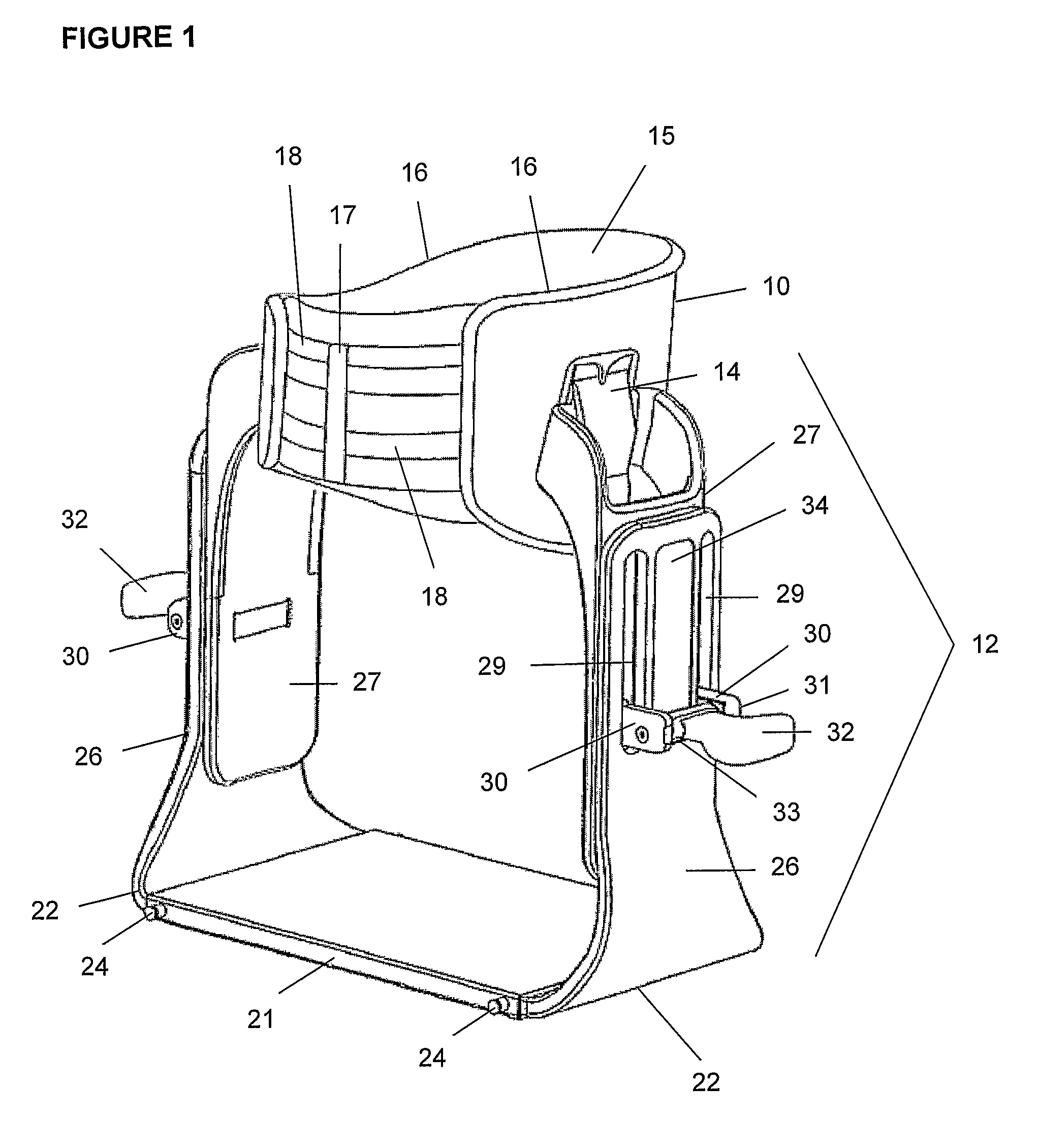
[0033]Preferably the device includes an adjustor for adjusting the length of the legs. The adjustor may be an actuator that changes the length of the legs, including hydraulic, pneumatic or electric rams. However preferably, the adjustor is one that is hand operated and may include a screw thread mechanism, or any other manually operated mechanism.

[0034]Preferably, the legs each include an upper portion and a lower portion that are moveable relative to each other and change the overall length of the legs.

[0035]Preferably, the adjustor allows the upper and lower leg portions to interfit in mating relationship. For example, the upper and lower portions of the legs may interfit in a telescopic manner in which one portion fits inside the other. A locking device such as a hole and pin arrangement may be used to the fix the relative positions of the upper and lower portions. Preferably, the adjustor comprises the upper and lower leg portions having mating interfaces that resist relative u...


PUM


Abstract

A lumbar traction device that can alleviate lower back pain is provided. The device includes a harness or girdle that is fitted about the torso region of a patient and an adjustable support assembly in the form of adjustable legs that allow the degree of traction to be adjusted by the patient. The device is safe and easy to use by a patient without constant medical supervision and is particularly suitable for use in domestic or office environments.

Description

FIELD OF THE PRESENT INVENTION[0001]The present invention relates to the field of orthotics, and in particular, to the field of orthotic devices that can alleviate lower back pain by reducing the load on a person's back.BACKGROUND OF THE PRESENT INVENTION[0002]Back pain may be caused by many conditions including bulging, ruptured or herniated discs between vertebrae in the lumbar region of a patient's spine. Such conditions are treated by means of either invasive surgery which has inherent risks or less invasive manipulative techniques. Temporary and permanent pain relief can be achieved using traction devices which are widely used by clinicians such as physiotherapists during patient consultations. One of the shortcomings of the traction devices used by clinicians is that they are often large and expensive, making these devices unsuitable for home use.[0003]An example of the traction device suitable for home use is described in U.S. Pat. No. 6,315,750 by J. T. Gray. The US patent d...

Claims


Application Information

Patent Timeline
Patent Type & Authority Patents(United States)
IPC IPC(8): A47D15/00A61F5/00B60R21/00A47C31/00
CPCA61F5/028A61F5/026A61F5/024A61H1/0292A61H1/0218A61H2201/1621A61H2203/0431A61F5/042
Inventor RAWLINGS, MARCUS, ANDREW
Owner RAWLINGS MARCUS ANDREW
Why Eureka
Try Eureka