
Hydraulic circuit for operating a tool

a technology of hydraulic circuit and tool, applied in mechanical equipment, couplings, constructions, etc., can solve the problems of inappropriate selection of settings by operators, and achieve the effect of reducing time-consuming tasks, simple construction, and reducing related risks

Inactive Publication Date: 2014-02-25
VOLVO CONSTR EQUIP AB
View PDF10 Cites 18 Cited by
  • Summary
  • Abstract
  • Description
  • Claims
  • Application Information

AI Technical Summary

Benefits of technology

[0003]It is desirable to provide a hydraulic circuit and a method for operating a hydraulic circuit by which this time consuming task is substantially reduced and the related risk is substantially reduced as well.
[0004]It is desirable to provide a hydraulic circuit which is simple in construction and enables to be controlled with an electronic control unit in a comparatively simple way.
[0005]According to an aspect of the invention, a hydraulic circuit is provided and, according to another aspect of the invention, a method for operating a hydraulic circuit is provided. One of the advantages of aspects of the invention is that an operator of the construction equipment is offered a high flexibility to realize settings for a plurality of different tools in an easy and quick manner.
[0006]More in detail, these solutions offer a flexible way to set and control the hydraulic circuit in a construction equipment. This is achieved especially by the fact that the settings and operating parameters of a nearly unlimited number of different tools can be programmed and stored, and then a certain tool which has been connected to the construction equipment can easily be selected by the operator, and the hydraulic parameter settings of the construction equipment for this tool can be adjusted in a quick and easy manner.
[0008]Another advantage of aspects of the invention is that a proportional foot pedal valve for the tool control can be easily included in order to keep a maximum flow limitation in both directions of the pilot pressure, wherein a de-activation function of the hydraulic circuit is kept, i.e. even if the pedal is pressed in order to operate a tool, the hydraulic circuit can be de-activated, if necessary, by means of the first proportional valve by switching the same such that substantially no hydraulic pressure is applied at its output.

Problems solved by technology

This is usually very time consuming and implies the risk that inappropriate settings are selected by the operator.

Method used


Image

  • Hydraulic circuit for operating a tool
  • Hydraulic circuit for operating a tool
  • Hydraulic circuit for operating a tool

Examples


Embodiment Construction

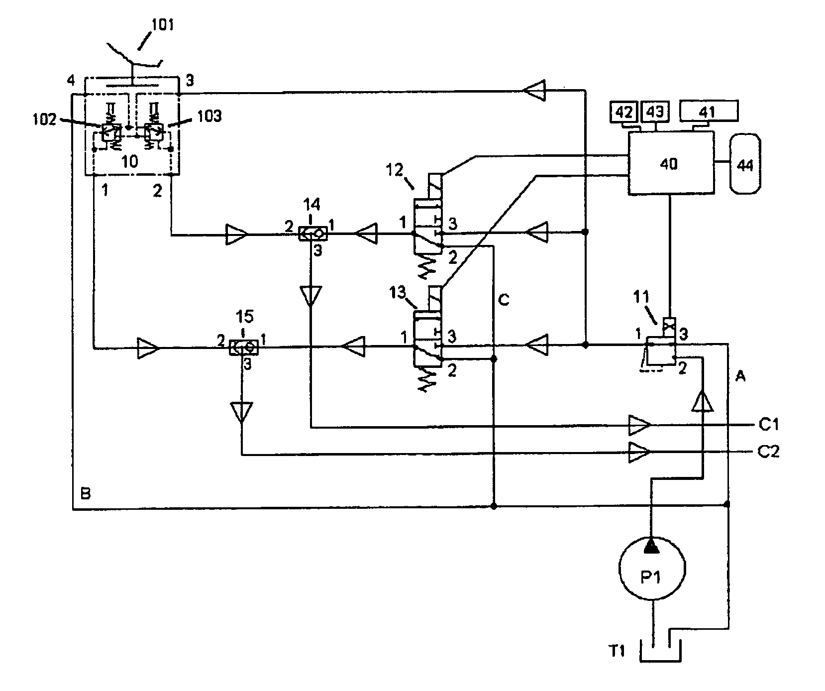
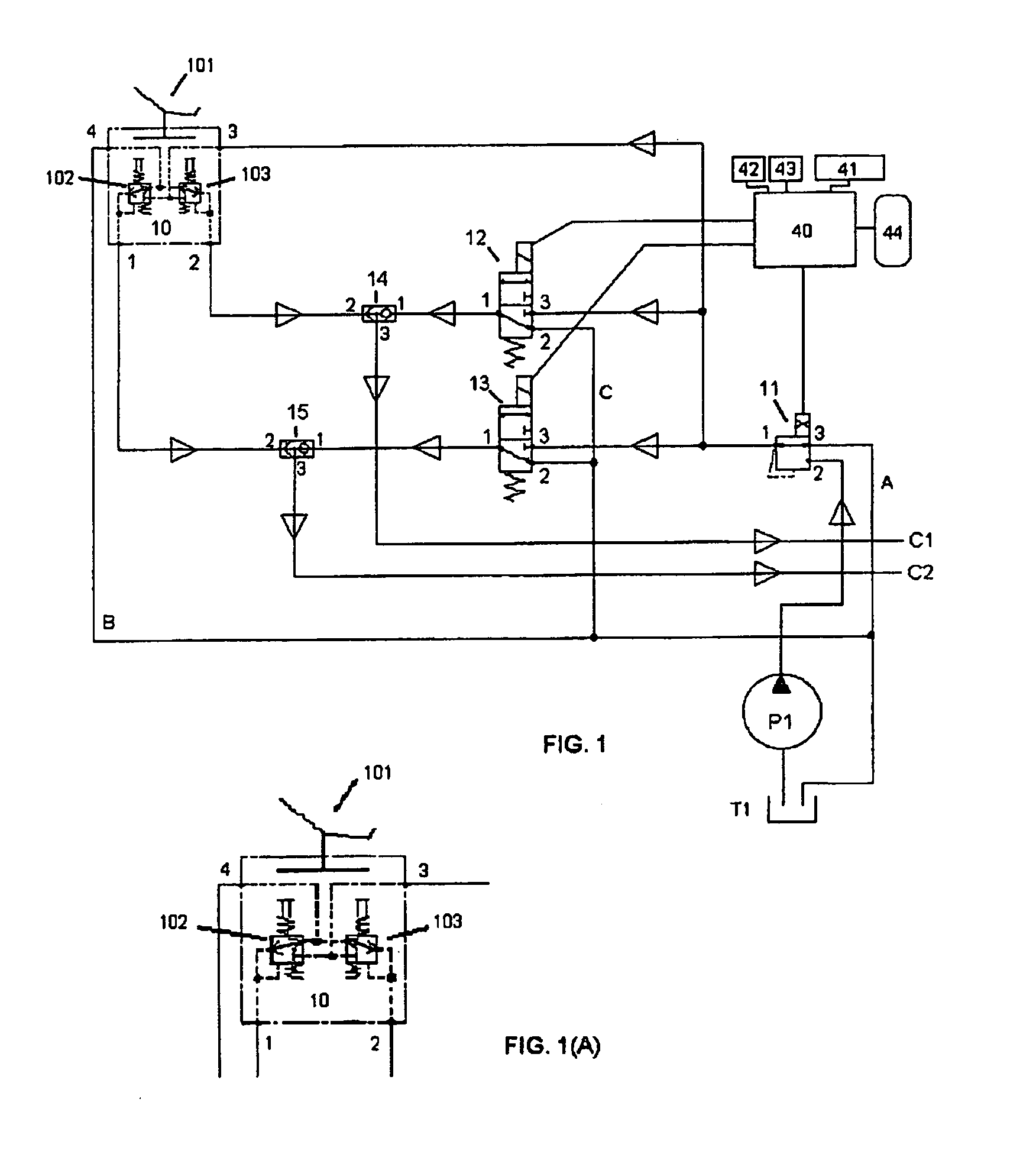
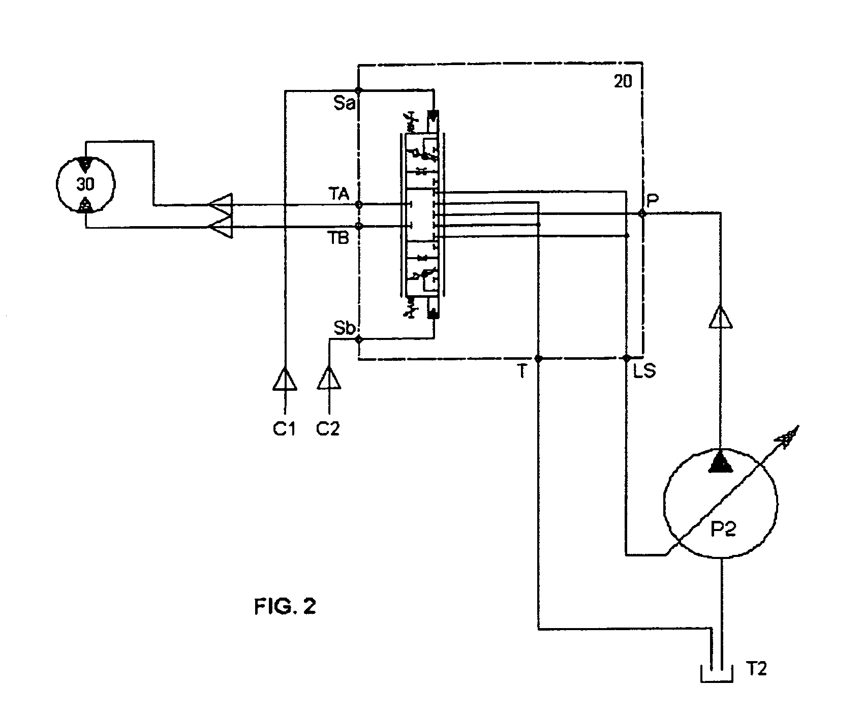
[0018]FIG. 1 shows an exemplary and preferred embodiment of a hydraulic circuit according to the invention for operating or actuating a tool. The circuit is provided for setting a hydraulic flow and for generating a hydraulic pilot pressure at one or both of its output lines C1 and C2 which lines C1 and C2 are continued in FIG. 2 and are connected with a first and a second spool, respectively, of a main control valve 20 which actuates a tool 30 by means of a hydraulic main pressure in a known manner. The tool 30 operated by the hydraulic circuit according to FIG. 1 can be a one-way tool like a hammer or a two-way tool like a shear. Furthermore, the tool 30 can be a proportional tool, and it can be a tool for high pressure, high power and / or high flow (like e.g. a hammer or a shear) or a tool for low pressure, low power and / or low flow (like e.g. a rotary tool or a grass clipper).

[0019]The hydraulic circuit according to FIG. 1 comprises a first proportional valve 11, a first and a se...


PUM


Abstract

A hydraulic circuit for operating a tool is provided that is particularly useful in construction equipment such as an excavator, crane, wheel loader, drilling machine, or others. Furthermore, a control unit and a method for controlling the hydraulic circuit and construction equipment including such a hydraulic circuit is disclosed.

Description

BACKGROUND AND SUMMARY[0001]The invention relates to a hydraulic circuit for operating a tool especially of a construction equipment like e.g. an excavator, crane, wheel loader, drilling machine, grass cutter or others. Furthermore, the invention relates to a control unit and a method for controlling the hydraulic circuit and to a construction equipment comprising such a hydraulic circuit.[0002]If a tool which is mounted at a construction equipment is exchanged by another tool, the operator of the construction equipment has to change and adjust accordingly the hydraulic parameter settings of the construction equipment like the pressure, the flow, the operation mode and other parameter settings which are specifically required for operating the new tool. This is usually very time consuming and implies the risk that inappropriate settings are selected by the operator.[0003]It is desirable to provide a hydraulic circuit and a method for operating a hydraulic circuit by which this time c...

Claims


Application Information

Patent Timeline
Patent Type & Authority Patents(United States)
IPC IPC(8): F15B13/042
CPCF15B2211/6346F15B2211/513E02F9/26E02F9/2296F15B2211/6054F15B2211/3144F15B13/0431F15B2211/329F15B13/0422F15B21/087F15B2211/20546F15B2211/50554F15B2211/7058F15B13/042F15B13/044
Inventor RICHTER, ALFREDLASTRE, FREDERIC
Owner VOLVO CONSTR EQUIP AB
Learn More