Gearing

a technology of gearing and gearing, applied in the field of gearing, can solve the problems of high level of compactness and complexity of gearing

Active Publication Date: 2014-02-25
WITTENSTEIN SE
View PDF22 Cites 32 Cited by
  • Summary
  • Abstract
  • Description
  • Claims
  • Application Information

AI Technical Summary

Benefits of technology

[0013]The present invention is therefore based on the object of creating a gearing of the type stated in the introduction, which eliminates the stated disadvantages of the hitherto known gearings, planetary gearings, eccentric gearings and harmonic drive gearings, wherein it should be possible to freely select a very high drive-input-side rotational speed range up to approximately 6000 rpm.
[0016]Furthermore, the gearing should have a very high level of compactness and complexity while having the smallest possible installation space and lowest possible weight, corresponding to its power-to-size ratio.
[0018]Furthermore, a gearing of said type should be operable with low wear and in a fatigue-endurable manner with high overload capabilities and a long service life. High torsional stiffness and tilting resistances should be ensured for large diameters and a high degree of compactness.
[0020]In the present invention, it has proven to be particularly advantageous to create a transmission in which a multiplicity of tooth segments are provided between a drive input and a stationary part or a drive output, which tooth segments, the transmission of the torque and the setting of the transmission ratio, move linearly into corresponding toothings of the drive output element or of the stationary part during the linear or rotational movement of the drive input element, in order, with a corresponding offset of the actual tooth flanks of the tooth segment, to transmit a torque with a correspondingly selected transmission ratio.
[0024]Furthermore, it should also be considered that a multiplicity of tooth segments with one or more teeth can slide by means of a connecting element, for example by means of a chain, on the polygon. In this way, it is possible to realize very large torques, in the case of variable transmission ratios, from approximately i=10 to i=200.

Problems solved by technology

Furthermore, the gearing should have a very high level of compactness and complexity while having the smallest possible installation space and lowest possible weight, corresponding to its power-to-size ratio.

Method used


Image

  • Gearing
  • Gearing
  • Gearing

Examples


Embodiment Construction

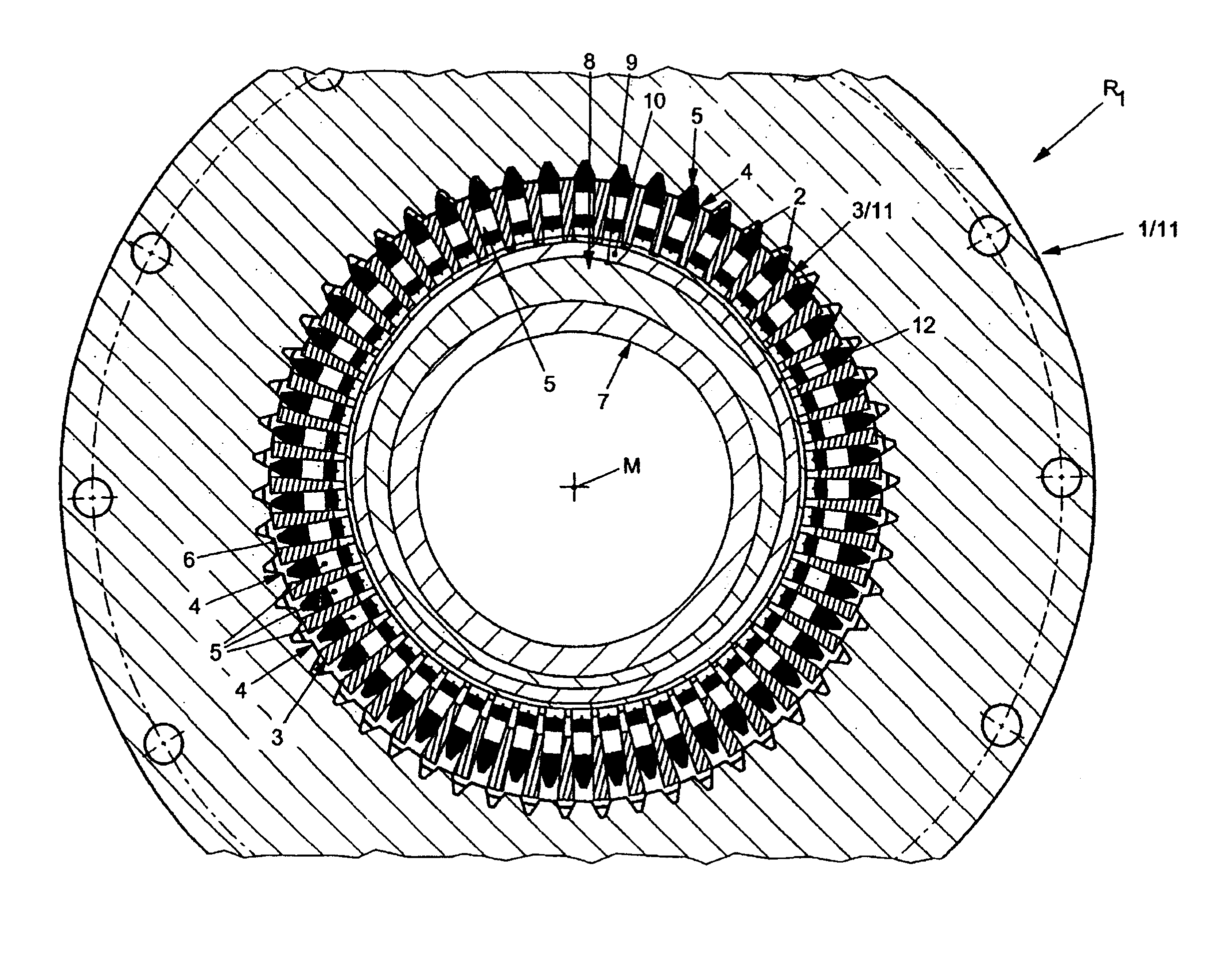
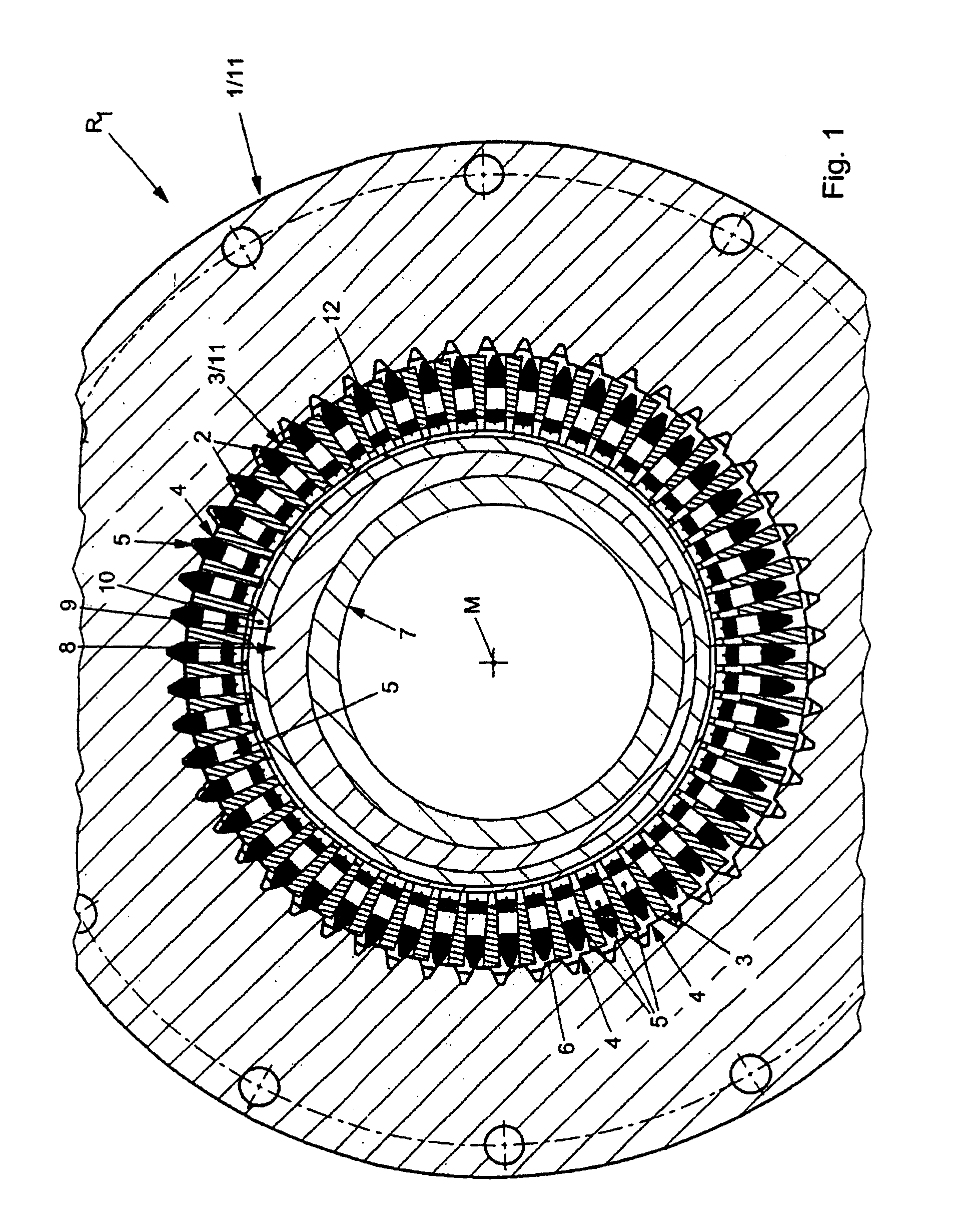
[0046]According to FIG. 1, a gearing R1, embodied as a coaxial gearing, has a ring gear 1 which has an inner toothing 2.

[0047]An element 3 is inserted in the manner of a circular ring within the ring gear 1, with a multiplicity of tooth segments 5 which are arranged radially adjacent to one another and in corresponding guides 4 being inserted in the circular-ring-like element 3. The tooth segments 5 are mounted so as to be movable radially back and forth within the guide 4, and are provided at one end with a tooth flank 6.

[0048]A drive input element 7, embodied as a shaft or hollow shaft, is provided within the element 3 with the tooth segments 5 held therein, which drive input element 7 has an outer profiling 8, which is formed for example with a contour, an elevation, in the manner of a polygon or cam.

[0049]If appropriate, a bearing arrangement 10 is provided between an outer contour 9 of the profiling 8 of the drive input element 7 and the element 3, or at one end of the tooth se...


PUM


Abstract

In a gearing, in particular coaxial gearing, hollow shaft gearing, hypoid gearing, axial gearing or linear gearing, with a driving element (7), an element (3) and an output element (11), a stepping-up and transmission of a driving torque between driving element (7) and output element (11) are to take place via a plurality of movable tooth segments (5).

Description

BACKGROUND OF THE INVENTION[0001]The present invention relates to a gearing, in particular coaxial gearing, hollow-shaft gearing, hypoid gearing, axial gearing or linear gearing, having a drive input element, an element and a drive output element.[0002]Conventional gearings of diverse forms and designs are known and available commercially.[0003]Use is made commercially substantially of three different gearing technologies. Firstly, commercially, planetary gear sets are known in which, for example within a ring gear, one or more planet gears are provided coaxially by means of a usually centrally arranged sun gear for transmitting a torque to a planet gear carrier or drive output element.[0004]In such epicyclic or planetary gear sets, high transmission speeds are not possible, and it is not possible for high torques to be transmitted with small hollow shaft diameters. Furthermore, gearings of said type are afflicted with low strength and a low level of robustness, with said gearings h...

Claims


Application Information

Patent Timeline
Patent Type & Authority Patents(United States)
IPC IPC(8): F16H48/12F16H23/00F16H37/00F16H33/00F16H1/32F16H35/02F16H35/00F16H3/70
CPCF16H49/001F16H2025/066F16H25/06Y10T74/19555Y10T74/19005Y10T74/19893Y10T74/19Y10T74/19219
Inventor BAYER, THOMASSCHMIDT, MICHAEL
Owner WITTENSTEIN SE
Why Eureka
Try Eureka