

Connecting rod fracture splitting apparatus and fracture splitting method
a technology of connecting rods and fractures, which is applied in mechanical devices, manufacturing tools, transportation and packaging, etc., can solve the problems of increasing friction or seizure of the connecting rod bearing, deteriorating the circularity after being fractured, and deteriorating the circularity after being assembled with the crank pin
- Summary
- Abstract
- Description
- Claims
- Application Information
AI Technical Summary
Benefits of technology
Problems solved by technology
Method used
Image

Examples
Embodiment Construction
[0026]Hereinafter, a preferred embodiment of a connecting rod fracture splitting apparatus according to the present invention will be described using the same reference numerals for elements which are substantially the same as or correspond to those in the conventional example based on the drawings.
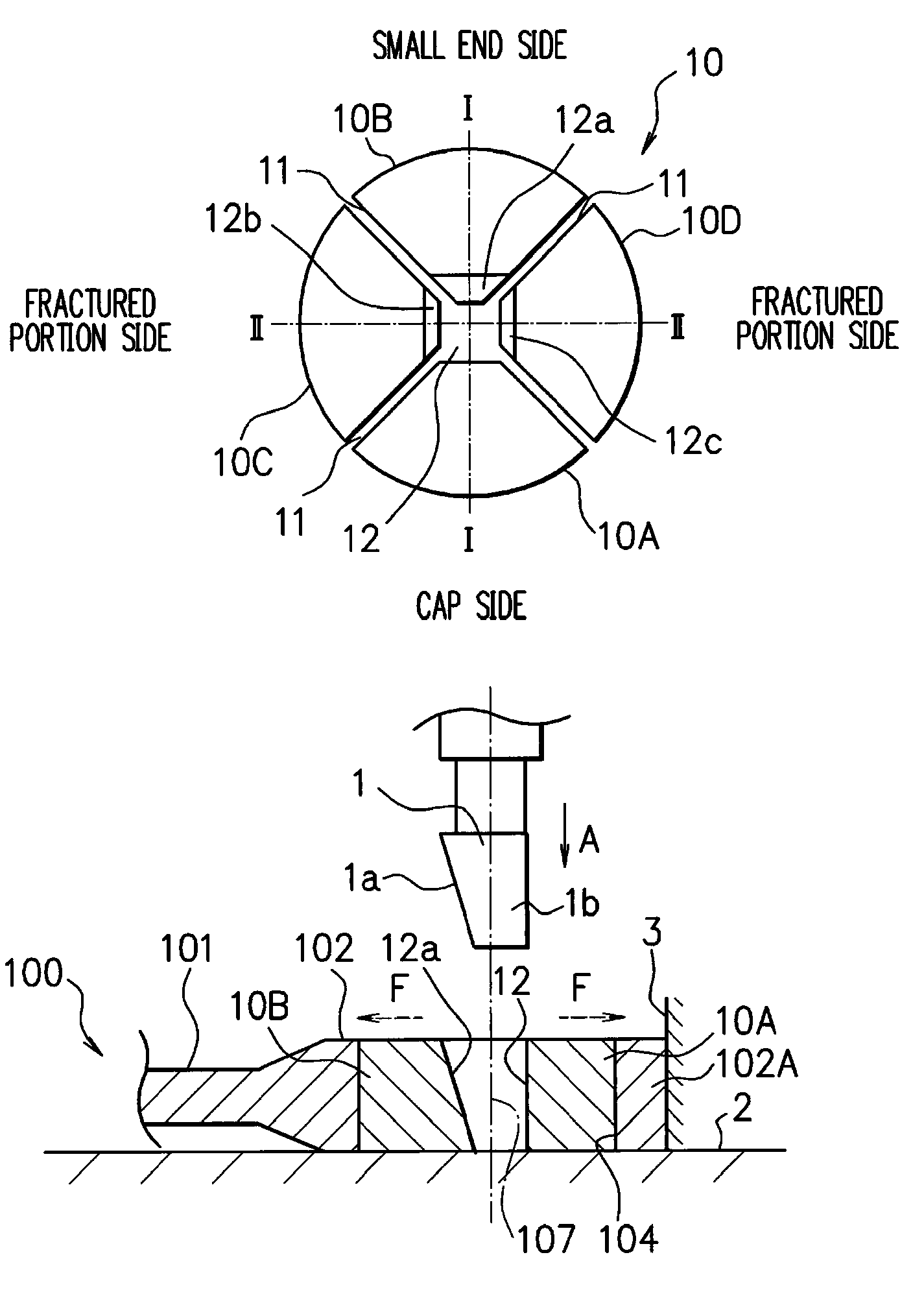
[0027]First, also in this embodiment, as already described (see FIG. 8 and FIG. 10), a connecting rod 100 has a big end 102 and a small end 103 on both ends of a connecting rod body 101. In the big end and the small end, there are formed a crank pin hole 104 and a piston pin hole 105, respectively. After being formed by forging, a cap 102A is integrated with the big end 102 as illustrated in FIG. 8, but the cap is separated from the connecting rod body 101 by splitting with the splitting apparatus. In an inner peripheral face of the crank pin hole 104 of the connecting rod 100, for example a pair of V-shaped notch grooves 107 is formed in advance in an axial direction of a crank pin (a di...
PUM
| Property | Measurement | Unit |
|---|---|---|
| diameter | aaaaa | aaaaa |
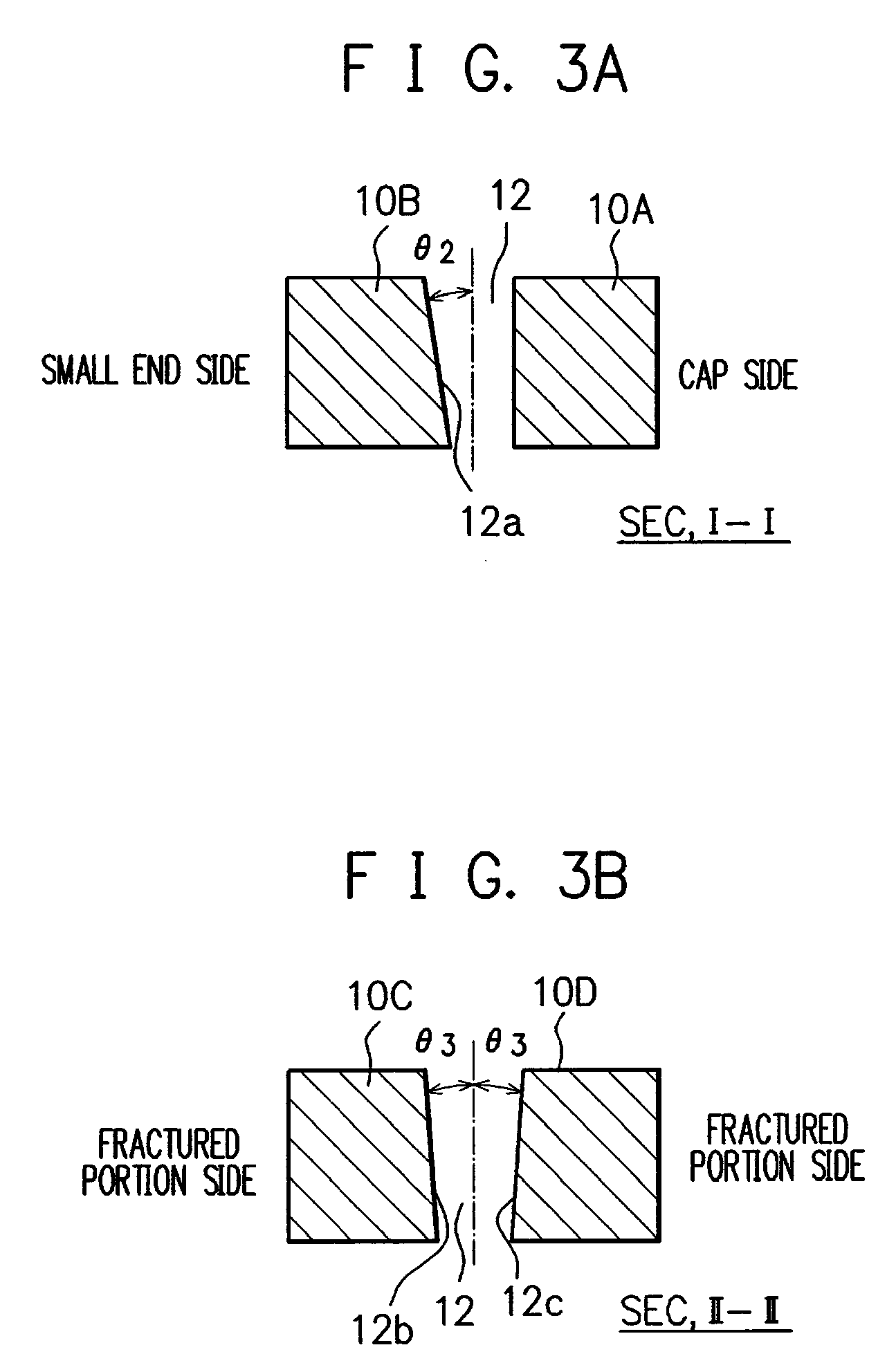
| inclination angle θ3 | aaaaa | aaaaa |
| inclination angle θ3 | aaaaa | aaaaa |
Abstract
Description
Claims
Application Information