Method and apparatus for providing electronic ignition of early automobile engines

a technology of electronic ignition and automobile engine, which is applied in the direction of mechanical equipment, machines/engines, lighting and heating apparatus, etc., can solve the problems of increasing the difficulty of finding replacement parts, rendering them completely undetectable by visual inspection, etc., and achieve the effect of facilitating the description of their operation

Active Publication Date: 2014-03-04
KOSSOR MICHAEL GORDON
View PDF6 Cites 1 Cited by
  • Summary
  • Abstract
  • Description
  • Claims
  • Application Information

AI Technical Summary

Benefits of technology

[0011]It is the objective of the present invention to offer a solution to this problem by providing a maintenance free, programmable electronic ignition module for early automobiles that utilizes all the existing components and wiring to retain the appearance and operation of the original system but with superior performance. The invention replaces the original roller / commutator contacts of the original vintage system and actuates the original coils that fire the original spark plugs using the original wiring in a similar manor. Electronic ignition module operation is user programmable to emulate the original roller / commutator performance or provide automatic spark advance similar to modern automobile operation for optimum power and efficiency while freeing the operator of the burden of manual adjustment of spark timing. Ignition module programming is accomplished without any external switches, jumpers or modification to the vintage automobile by simply sensing the presence or absence of ignition coils when power is applied. The electronic ignition module resides fully contained within the confines of the original timer housing without any modifications what so ever, rendering it completely undetectable by visual inspection.

Problems solved by technology

Replacement components are becoming increasingly more difficult to find, can be expensive and often are time consuming to replace and align; requiring expensive special tools and the knowledge of how to properly use them.
The electronic ignition module resides fully contained within the confines of the original timer housing without any modifications what so ever, rendering it completely undetectable by visual inspection.

Method used


Image

  • Method and apparatus for providing electronic ignition of early automobile engines
  • Method and apparatus for providing electronic ignition of early automobile engines
  • Method and apparatus for providing electronic ignition of early automobile engines

Examples


Embodiment Construction

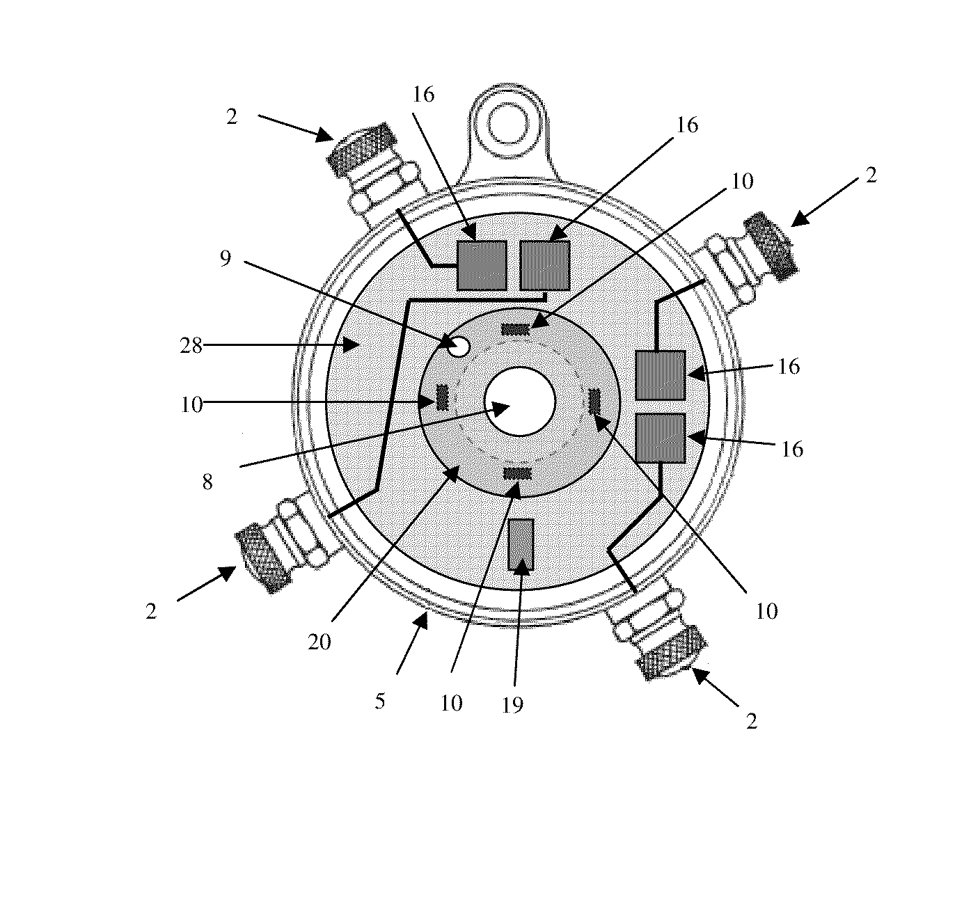
[0022]Referring to FIG. 6, which shows one embodiment of the present invention, commutator housing 5 employs electrical terminals 2 that are normally isolated from commutator housing 5. Ignition module 28 is physically mounted within housing 5. Electronic sensors 10 located on ignition module 28 are actuated by sensor activator 9 located on rotor 20 that is physically mounted to engine CAM shaft 8. Operation is as follows: Rotor 20 rotates with engine CAM shaft 8. Sensor activator 9 functions to activate a particular sensor 10 when it moves within close proximity to it. Microcontroller 19 located on ignition module 28 detects actuation of the particular sensor 10 and functions activate a corresponding electronic switch 16 that electrically connects its corresponding terminal 2 to commutator housing 5 which is also normally electrically connected to engine ground. Microcontroller 19 determines the mapping between sensor 10 activation and which electronic switch 16 is activated. The p...


PUM


Abstract

An electronic ignition module for vintage automobiles that utilizes existing components and wiring to retain the look and operation of the original system but with superior performance. The ignition module replaces the original roller and contacts of a vintage automobile ignition timer with modern control electronics that actuate the original coils and original spark plugs using the original wiring in the original manor. Electronic ignition operation is user programmable to emulate the original roller / timer performance or provide automatic spark advance similar to modern automobile operation for optimum power and efficiency while freeing the operator from manual adjustment of spark timing. Ignition module programming is accomplished without any external switches, buttons, jumpers or modification to the vintage automobile by simply sensing the presence or absence of ignition coils connected to the system when power is applied. The electronic ignition module resides fully contained within the confines of the original timer housing without any modifications what so ever, rendering it completely undetectable by visual inspection.

Description

BACKGROUND[0001]1. Field of the Invention[0002]This invention relates to automobile ignition systems. More specifically, this invention relates to early automobile electronic ignition systems.[0003]2. Prior Art[0004]FIG. 1 depicts an example of an early automobile ignition system. An example of an automobile that used such a system was the Ford Model T. For the purposes of discussion that follows, the term early refers to automobiles produced between the years of 1900 and 1930. The main components of the system comprise commutator 5, coil primary wires 1, coil box 6 containing ignition coils, spark plug wires 7 used to carry high voltage spark to their corresponding spark plugs 14. Note that commutator 5 is sometimes referred to as a Timer.[0005]The basis of operation of this system is 100 year old technology and is well known to those skilled in the art. A brief summary of the essential elements as they pertain to the subject of the present invention will be covered. A simplified s...

Claims


Application Information

Patent Timeline
Patent Type & Authority Patents(United States)
IPC IPC(8): F02P3/04
CPCF02P5/1502F02P7/035F02P7/021Y02T10/46F02P5/005Y02T10/40
Inventor KOSSOR, MICHAEL, GORDON
Owner KOSSOR MICHAEL GORDON
Why Eureka
Try Eureka