
Phosphor, method of producing the same, and light emitting apparatus

a technology of phosphor and phosphor, which is applied in the direction of solid-state devices, inorganic chemistry, discharge tubes/lamp details, etc., can solve the problems of patent document 4 failing to describe the reflectance of phosphor itself, temperature rise in light emitting devices and light converters during operation, and inability to set input energy at high states. , to achieve the effect of high efficiency, stable characteristics and high efficiency

Active Publication Date: 2014-03-04
DENKA CO LTD +1
View PDF137 Cites 9 Cited by
  • Summary
  • Abstract
  • Description
  • Claims
  • Application Information

AI Technical Summary

Benefits of technology

[0015]The present invention was made to solve the aforementioned problems, and it is an object of the present invention to provide a nitride phosphor and an oxynitride phosphor which stably emit light with high efficiency in response to light of 430 to 480 nm from a semiconductor light emitting device, a method of producing these phosphors, and a light emitting apparatus realizing high efficiency and stable characteristics.
[0027]The phosphor according to the present invention as described above stably emits light with high efficiency by the light ranging from 430 to 480 nm, and the light emitting apparatus using a light converter having the phosphor according to the present invention is able to absorb light emitted from the light emitting device with high efficiency and offers stable white light with high efficiency.

Problems solved by technology

For achieving this, development of the entire structure and material of light emitting apparatus has been proceeded, however, temperature rise in a light emitting device and light converter during operation is still inevitable.
However, in the trivalent cerium-activated (Y, Gd)3(Al, Ga)5O12 phosphor, in particular, there is a technical problem that it is impossible to set input energy at high states because the luminance at 100° C. decreases to about 85%, compared to the luminance (brightness) of 100% at 25° C. Therefore, an oxynitride phosphor or a nitride phosphor having excellent temperature characteristics attracts attention and active development has been made.
However, in such an oxynitride phosphor or nitride phosphor, reflectance in the visible region is not sufficiently high despite the excellent characteristics, so that there is a technical problem that it absorbs light emitted from the phosphor itself or the light emitted from other phosphor.
However, Patent document 4 fails to describe reflectance of the phosphor itself.

Method used

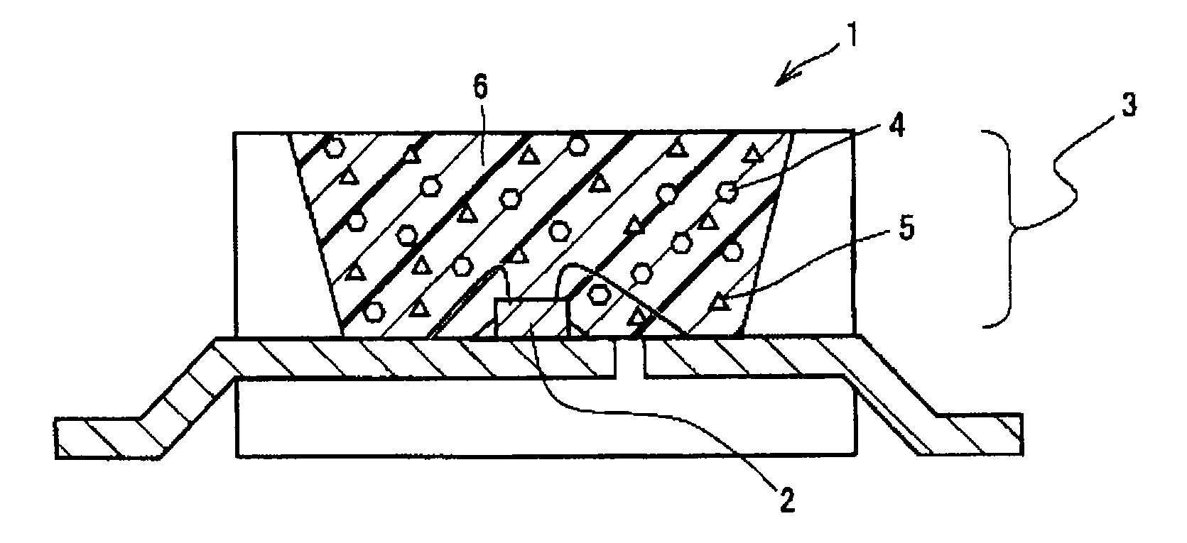
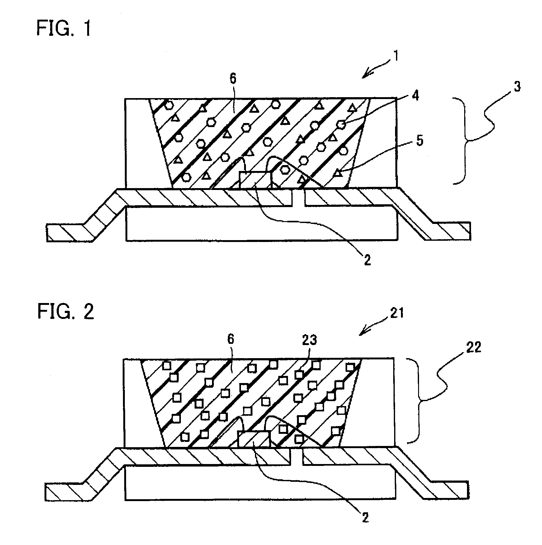

Image

  • Phosphor, method of producing the same, and light emitting apparatus
  • Phosphor, method of producing the same, and light emitting apparatus

Examples


example 1

[0074]191.64 g of silicon nitride (Si3N4) powder, 6.75 g of aluminum nitride (AlN) powder covered with 2.0% by weight of silicon dioxide (SiO2) having an average particle diameter of 24 nm, and 1.62 g of europium oxide (Eu2O3) powder were weighed, and introduced into a V-shaped mixer in a glove box the entirety of which is substituted with nitrogen, and mixed for twenty minutes. The obtained mixture was put into a crucible of boron nitride and calcined for eight hours at 2000° C. in nitrogen atmosphere at 10 atm. The obtained calcined substance was ground by a ball mill or the like. The ground powder was put into a crucible of boron nitride, and calcined for ten hours at 1700° C. in nitrogen atmosphere at 5 atm. The obtained calcined substance was ground by a ball mill or the like. After grinding, 1 L of pure water was put into a 1 L-beaker, followed by the calcined substance, and stirred. After stirring for a predetermined time, the stirring was stopped and the reaction was kept st...

example 2

[0076]118.60 g of silicon nitride (Si3N4) powder, 16.46 g of aluminum nitride (AlN) powder covered with 10.0% by weight of silicon dioxide (SiO2) having an average particle diameter of 100 nm, 2.12 g of europium oxide (Eu2O3) powder, and 14.47 g of calcium carbonate (CaCO3) powder were weighed, introduced into a V-shaped mixer in a glove box the entirety of which is substituted with nitrogen, and mixed for twenty minutes. The obtained mixture was put into a crucible of boron nitride and calcined for twelve hours at 1700° C. in nitrogen atmosphere at 10 atm. The obtained calcined substance was ground by a ball mill or the like. After grinding, 1 L of pure water was put into a 1 L-beaker, followed by the calcined substance, and stirred. After stirring for a predetermined time, the stirring was stopped and the reaction was kept still to remove fine particle components that have occurred during the grinding. This cleaning operation was repeated to remove most of the fine particle compon...

example 3

[0078]56.54 g of calcium nitride (Ca3N2) powder, 47.38 g of aluminum nitride (AlN) powder covered with 0.1% by weight of silicon dioxide (SiO2) having an average particle diameter of 45 nm, 54.05 g of silicon nitride (Si3N4) powder, and 2.03 g of europium oxide (Eu2O3) powder were weighed, and introduced into a V-shaped mixer in a glove box the entirety of which is substituted with nitrogen, and mixed for twenty minutes. The obtained mixture was put into a crucible of boron nitride and calcined for five hours at 1500° C. in nitrogen atmosphere. The obtained calcined substance was ground by a ball mill or the like. After grinding, 1 L of pure water was put into a 1 L-beaker, followed by the calcined substance, and stirred. After stirring for a predetermined time, the stirring was stopped and the reaction was kept still to remove fine particle components that have occurred during the grinding. This cleaning operation was repeated to remove most of the fine particle components. Thereaf...


PUM

PropertyMeasurementUnit
reflectanceaaaaaaaaaa
particle diameteraaaaaaaaaa
wavelengthaaaaaaaaaa

Abstract

There are provided a phosphor which is a divalent europium-activated oxynitride phosphor substantially represented by General formula (A): EuaSibAlcOdNe, a divalent europium-activated oxynitride phosphor substantially represented by General formula (B): MIfEugSihAlkOmNn or a divalent europium-activated nitride phosphor substantially represented by General formula (C): (MIIl-pEup)MIIISiN3, having a reflectance of light emission in a longer wavelength region of visible light than a peak wavelength of 95% or larger, and a method of producing such phosphor; a nitride phosphor and an oxynitride phosphor which emit light efficiently and stably by the light having a wavelength ranging from 430 to 480 nm from a semiconductor light emitting device by means of a light emitting apparatus using such phosphor, and a producing method of such phosphor; and a light emitting apparatus having stable characteristics and realizing high efficiency.

Description

[0001]This nonprovisional application is based on Japanese Patent Application No. 2006-317524 filed with the Japan Patent Office on Nov. 24, 2006, the entire contents of which are hereby incorporated by reference.BACKGROUND OF THE INVENTION[0002]1. Field of the Invention[0003]The present invention mainly relates to oxynitride phosphors and nitride phosphors used for a light emitting apparatus, and methods of producing the same, and further to a light emitting apparatus having a light converter using the above phosphor.[0004]2. Description of the Background Art[0005]A light emitting apparatus having a combination of a semiconductor light emitting device and a phosphor attracts attention as a next-generation light emitting apparatus for which low power consumption, compact size, high intensity and high color gamut are expected, and research and development thereof is actively proceeded. As primary light that is emitted from a light emitting device, usually light from ultraviolet to bl...

Claims


Application Information

Patent Timeline
Patent Type & Authority Patents(United States)
IPC IPC(8): H01J1/62C09K11/02C09K11/08H01L33/56H01J63/04H01L33/50H01L33/32C09K11/70
CPCC04B2235/3418C04B2235/5454C09K11/0883C01B21/0821C04B35/6262C01P2004/62C04B35/584C01P2002/52C01B21/0826C01P2004/64C04B2235/3852C04B2235/3208B82Y30/00C04B35/581C04B2235/767C04B35/597C09K11/7734C04B2235/3224C01P2006/60C01P2004/61C04B2235/442C04B2235/3873C01B21/0602C04B2235/3865C04B2235/766C04B35/62807F21K9/56C09K11/7728F21K9/64H01L2224/48247H01L2224/48257H01L2224/73265C09K11/77348G02F1/1336H01L33/32H01L33/502H01L33/504H01L33/507
Inventor MASUDA, MASATSUGUTERASHIMA, KENJI
Owner DENKA CO LTD
Learn More