Spherical rotational radiation therapy apparatus

a radiation therapy apparatus and rotating technology, applied in the field of medical devices, can solve the problems of imposing substantial functional limitations on the diagnosis and directional radiation treatment of diseases, affecting the accuracy of src positioning, and limiting the radiation beams emanating from the accelerator, so as to increase the location accuracy and strengthen the structural rigidity of the multi-axial gantry

Inactive Publication Date: 2014-03-04
LINATECH
View PDF12 Cites 38 Cited by
  • Summary
  • Abstract
  • Description
  • Claims
  • Application Information

AI Technical Summary

Benefits of technology

[0018]As a more detailed embodiment to insure structural rigidity of the multi-axial gantry and locational accuracy of the SRC, the X-axis gantry pivoting base support mechanism is configured to have at least two base support mechanisms each having a pivot-bearing engaging the DSG and a support strut supporting the pivot-bearing.
[0019]To further strengthen structural rigidity of the multi-axial gantry and increase locational accuracy of the SRC, the X-axis gantry pivoting base support mechanism further includes a bottom base for affixing the support struts upon it.

Problems solved by technology

In addition, radiation beams emanated from the accelerator are also constrained to a plane perpendicular to the Z-axis lacking the freedom of choosing their radiation incident angle.
Consequently, such constraints of the present-day radiation therapy equipment impose substantial functional limitations to the diagnosis and directional radiation treatment of diseases.
However, firstly the heavy weight of the accelerator causes the accelerator-hanging mechanism and its associated driving mechanism to become highly complex with high production cost.
Secondly, the pendulum-like movement of the accelerator head can cause instability of the radiation beams.
Thirdly, the tight coupling between the accelerator and its driving mechanism can cause interference to the whole treatment system further increasing production difficulty and cost.
Thus, the pendulum-like movement of the accelerator head would cause a loss of real-time functional synchrony between the accelerator and the digital image detection planar board, affecting the ability of the treatment system to perform treatment with real-time diagnosis and compensation.

Method used


Image

  • Spherical rotational radiation therapy apparatus
  • Spherical rotational radiation therapy apparatus
  • Spherical rotational radiation therapy apparatus

Examples


Embodiment Construction

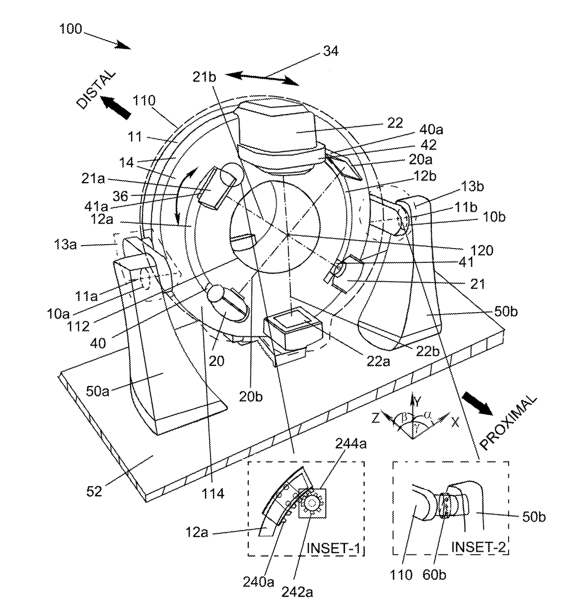
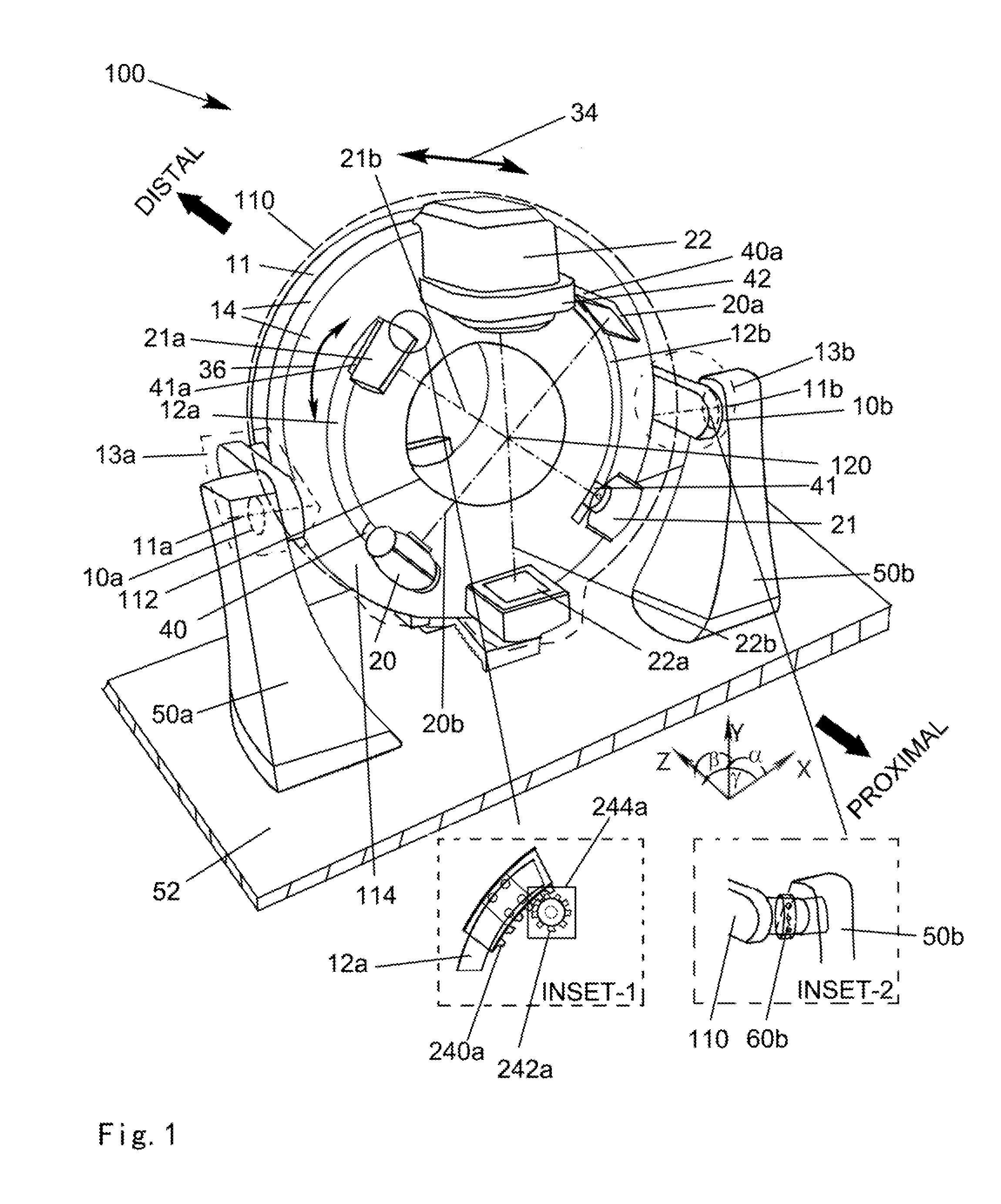
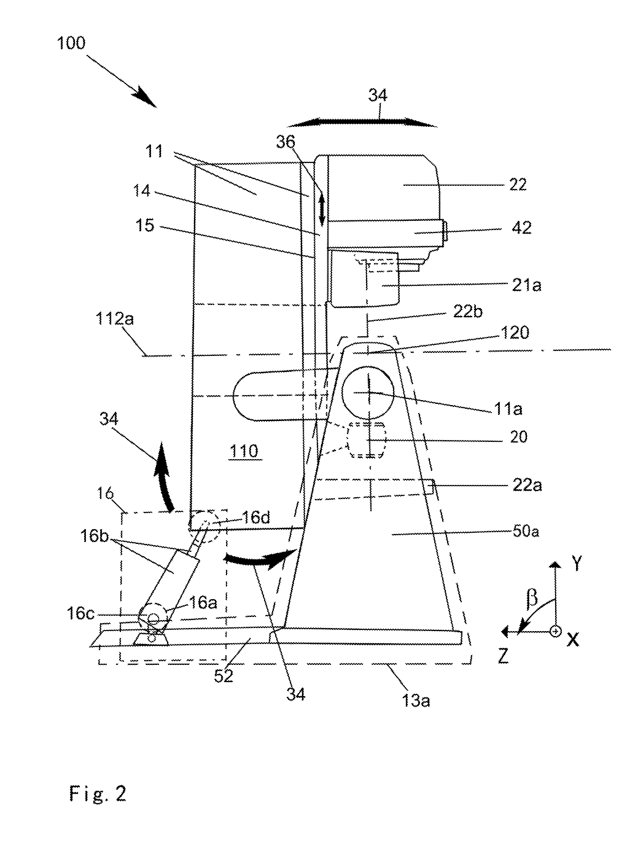
[0029]The following specific embodiments, in combination with the accompanying drawings, serve to further explain the present invention in details. FIG. 1 illustrates a front perspective view of an embodiment of the present invention spherical rotational radiation therapy apparatus (SRRTA) 100. To those skilled in the art, the SRRTA 100 is a gantry based radiation therapy apparatus with a multi-axial gantry 110 of a substantially cylindrical shape with an annular X-Y cross section. The multi-axial gantry 110 has a hollow cylindrical bore 112. The hollow cylindrical bore 112 has a longitudinal bore axis 112a (see FIG. 2). Notice that the multi-axial gantry 110 includes a proximal sub-gantry (PSG) 14 and a distal sub-gantry (DSG) 11 with the PSG 14 rotatably, around the longitudinal bore axis 112a, supported by the DSG 11 through a bearing interface between them. This arrangement thus supports a Z-rotation 36 of the PSG 14. As directional references, the proximal end and distal end of...


PUM


Abstract

A spherical rotational radiation therapy apparatus (SRRTA) with single spherical rotation center (SRC) is proposed. Referencing a combined X-Y-Z Cartesian and (r-α-β-γ) polar coordinates. The SRRTA includes a multi-axial gantry with rotatable proximal face around gantry bore; the proximal gantry face has at least one rotatable, along α-coordinate, pair of therapeutic level radiation-generating accelerator and image detector defining a therapeutic level radiation axis between the two; at least two arc-shaped sub-rails on the proximal gantry face; at least two rotationally slidable, against the arc-shaped sub-rails thus along α-coordinate, pairs of imaging level radiation-generating accelerators and image detectors defining an imaging level radiation axis between the two; the therapeutic level radiation axes and all imaging level radiation axes are configured to intersect at a single SRC along the longitudinal bore axis; an X-axis gantry pivoting driving mechanism is provided for driving the distal end of the multi-axial gantry.

Description

CROSS REFERENCE TO RELATED APPLICATIONS[0001]This application is based upon and claims the priority of a previously filed provisional patent application entitled “A Sphere Rotational Radiation Therapy Apparatus” by Jonathan Yao with application No. 61 / 618,717, filing date Mar. 31, 2012 whose content is herein incorporated by reference for all purposes.FIELD OF INVENTION[0002]This invention relates generally to the field of medical apparatus. More specifically, the present invention is directed to a multi-rotational axis positioning radiation therapy apparatus for performing image guided radiation therapy (IGRT) in conjunction with an electronic radiation therapy controller.BACKGROUND TECHNOLOGY[0003]While conducting radiation therapy of a patient tumor (target zone, or target organ) accurate location of the tumor is necessary. For location in a 3-dimensional space, a physician or radiologist at first scans and acquires, in a Computed Tomography (CT) room, a CT image data set of the ...

Claims


Application Information

Patent Timeline
Patent Type & Authority Patents(United States)
IPC IPC(8): G01T1/00
CPCA61N5/1082
Inventor YAO, JONATHAN
Owner LINATECH
Why Eureka
Try Eureka