Secondary communication signal method and apparatus

a signal and second communication technology, applied in the field of communication, can solve the problems of limiting the benefits obtainable by using this ppm remodulation technique, the mode s spectrum and pulse shape requirements, and the cost of simply replacing them is exorbitant, so as to increase the data rate, range or interference immunity

Inactive Publication Date: 2014-03-04
PIESINGER GREGORY HUBERT
View PDF17 Cites 7 Cited by
  • Summary
  • Abstract
  • Description
  • Claims
  • Application Information

AI Technical Summary

Benefits of technology

[0009]Briefly, to achieve the desired object of the present invention, a low level communication signal (secondary signal) is summed to an existing unaltered communication signal (...

Problems solved by technology

Although these systems could be greatly enhanced using today's advances in communication technology, the cost of simply replacing them would be exorbitant due to the large quantity of this legacy equipment still in use.
Although this technique enhances the current Mode S transponder reply signal by converting the existing...

Method used


Image

  • Secondary communication signal method and apparatus
  • Secondary communication signal method and apparatus
  • Secondary communication signal method and apparatus

Examples


Embodiment Construction

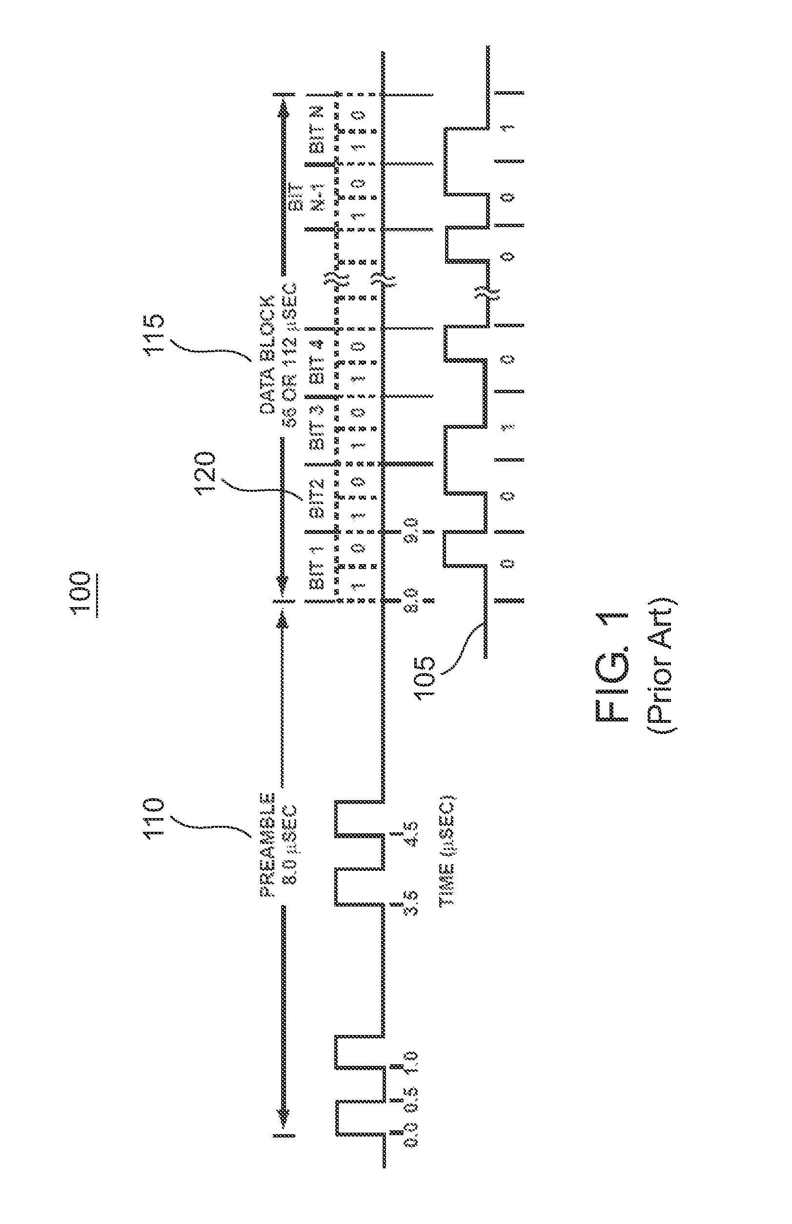
[0033]Mode S transponder PPM replies on 1090 MHz are defined in RTCA / DO-181C specification “Minimum Operational Performance Standards for Air Traffic Control Radar Beacon System / Mode Select (ATCRBS / Mode S) Airborne Equipment” which is incorporated by reference herein in its entirety.

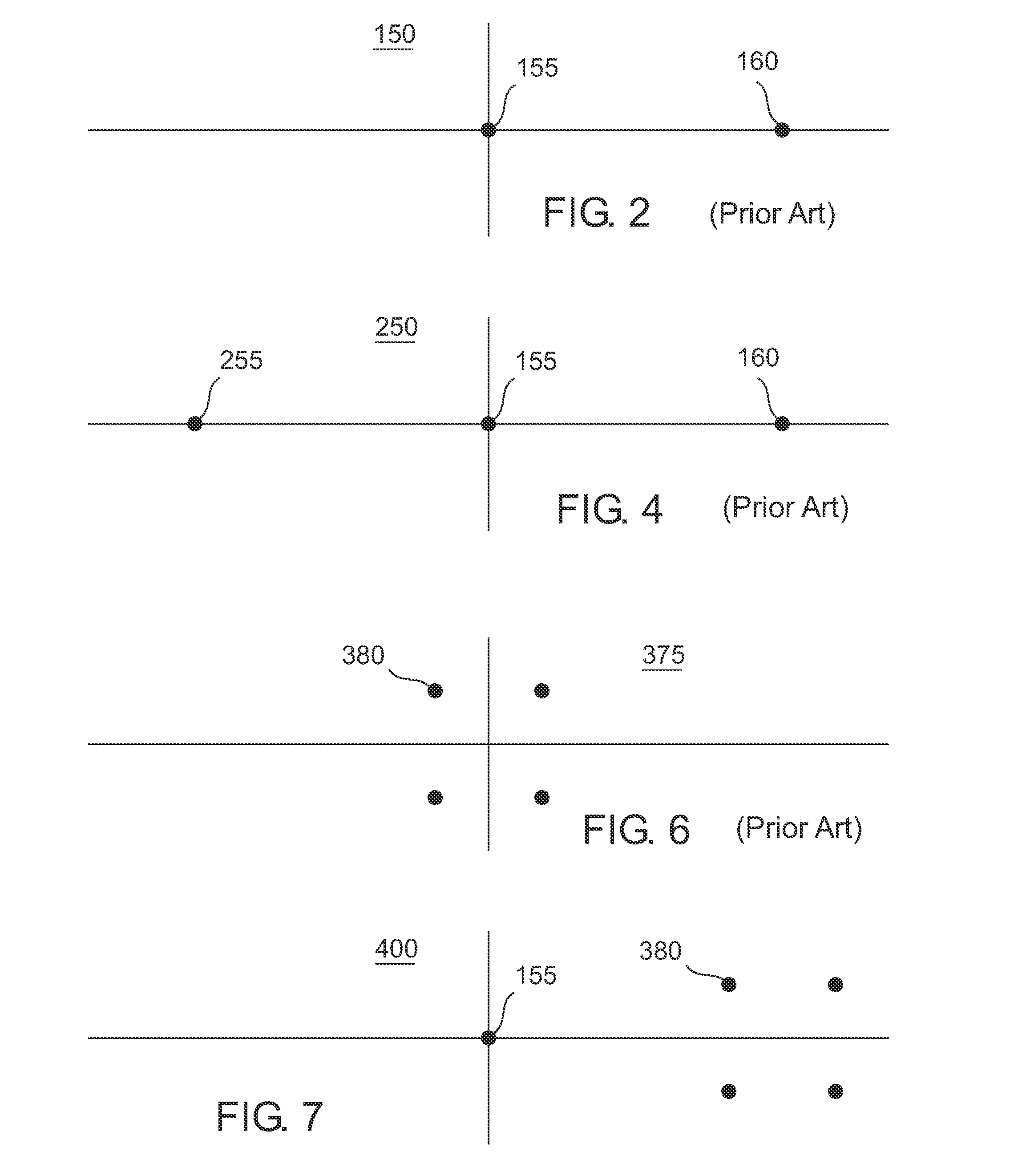
[0034]A Mode S reply waveform 100 corresponding to bit sequence (0010 . . . 001) 105 from this specification is illustrated in FIG. 1. This waveform consists of a preamble 110 followed by data block 115 which consists of either 56 or 112 PPM data bit intervals 120. A constellation diagram 150 is illustrated in FIG. 2 for this modulation signal. Constellation point 155 at zero amplitude and phase indicates no pulse is transmitted while constellation point 160 indicates an amplitude modulated pulse at zero phase is transmitted during preamble period 110 or data block period 115.

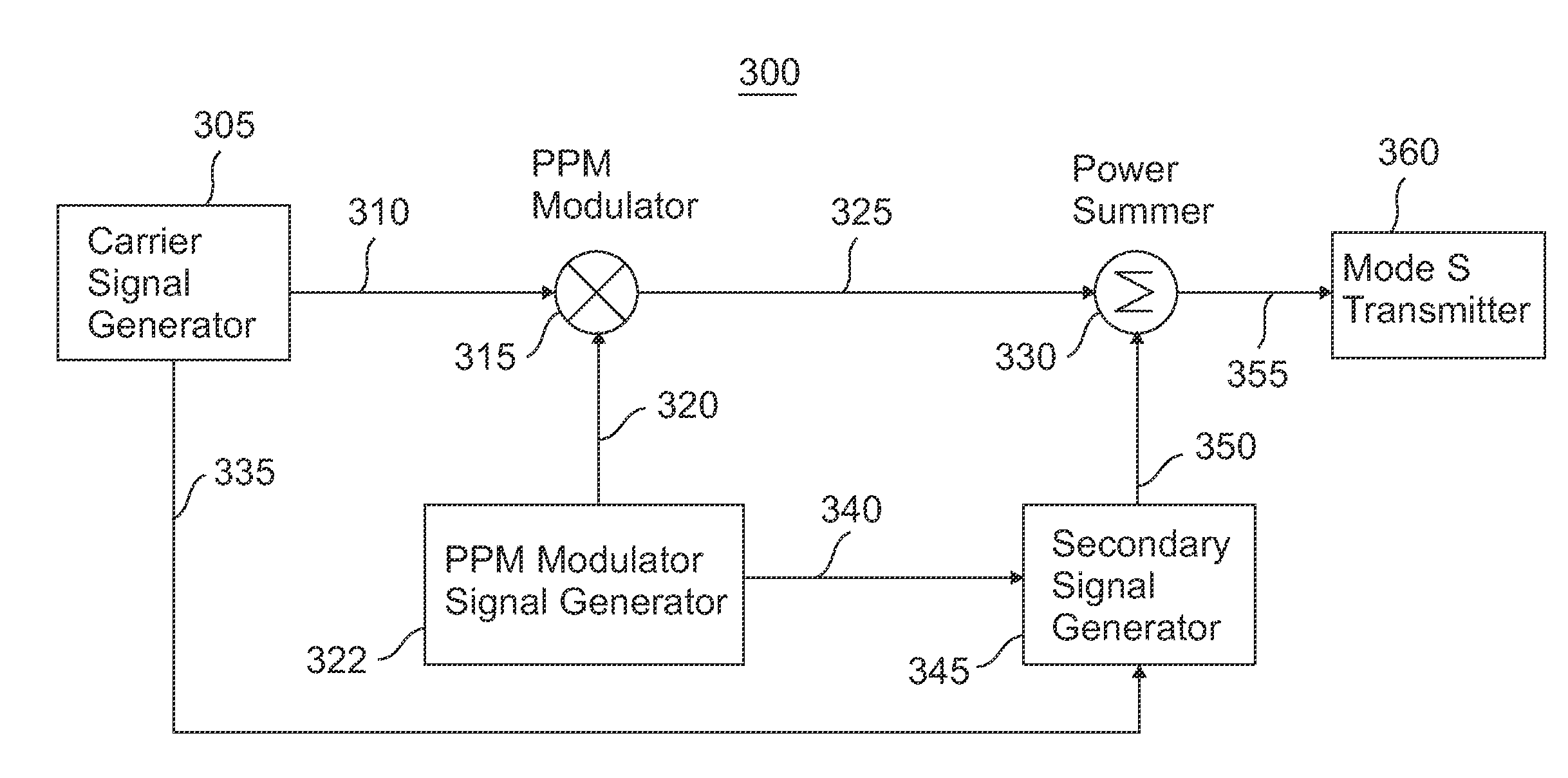
[0035]A block diagram of a prior art enhancement technique using overlay modulation, which was described in U.S. Pat. No. 8,031,10...


PUM


Abstract

A low level secondary communication signal is summed with an existing primary communication signal in a manner that prevents interference to the existing primary communication signal while providing secondary communication signal benefits such as increased data rate, range, or interference immunity. Examples are presented in which a M-QAM secondary signal is summed with either an ATC Mode S PPM reply or DPSK interrogation primary signal. Legacy Mode S transponders, TCAS, and ADS-B equipment continue to demodulate and decode the primary signal information in accordance with preexisting formats while new enhanced equipment obtains the benefits of the secondary signal.

Description

TECHNICAL FIELD OF THE INVENTION[0001]The present invention relates to the field of communications. More specifically, the present invention relates to summing a low level secondary communication signal to an existing primary communication signal in a manner that prevents interference to the existing primary communication signal while providing an overall communications benefit such as increased data rate, range, or interference immunity. In particular, this invention is applied to air traffic control (ATC) related communications.BACKGROUND OF THE INVENTION[0002]Most communication systems in widespread use today evolved from standards and equipment developed many years ago. This is especially true in the field of aircraft communications where equipment fielded one or two decades ago is still in use. Although these systems could be greatly enhanced using today's advances in communication technology, the cost of simply replacing them would be exorbitant due to the large quantity of th...

Claims


Application Information

Patent Timeline
IPC IPC(8): H04L27/34
CPCH04L27/34H04L25/4902H04L27/3483G01S13/765G01S13/782
Inventor PIESINGER, GREGORY, HUBERT
Owner PIESINGER GREGORY HUBERT
Why Eureka
Try Eureka