System and method for monitoring/controlling a sound masking system from an electronic floorplan

a technology electronic floor plan, which is applied in the field of sound masking system, can solve the problems of reducing the comfort level of acoustic perspective, affecting speech and conversational privacy, and suffering from a high level of noise distraction

Active Publication Date: 2014-03-04
777388 ONTARIO
View PDF37 Cites 11 Cited by
  • Summary
  • Abstract
  • Description
  • Claims
  • Application Information

AI Technical Summary

Problems solved by technology

Sound masking systems are widely used in offices and similar workplaces where an insufficient level of background sound results in diminished speech and conversational privacy.
Such environments typically suffer from a high level of noise distractions, and lower comfort levels from an acoustic perspective.
The background sound has the effect of limiting the ability to hear two sounds of similar sound pressure level and frequency simultaneously.

Method used


Image

  • System and method for monitoring/controlling a sound masking system from an electronic floorplan
  • System and method for monitoring/controlling a sound masking system from an electronic floorplan
  • System and method for monitoring/controlling a sound masking system from an electronic floorplan

Examples


Embodiment Construction

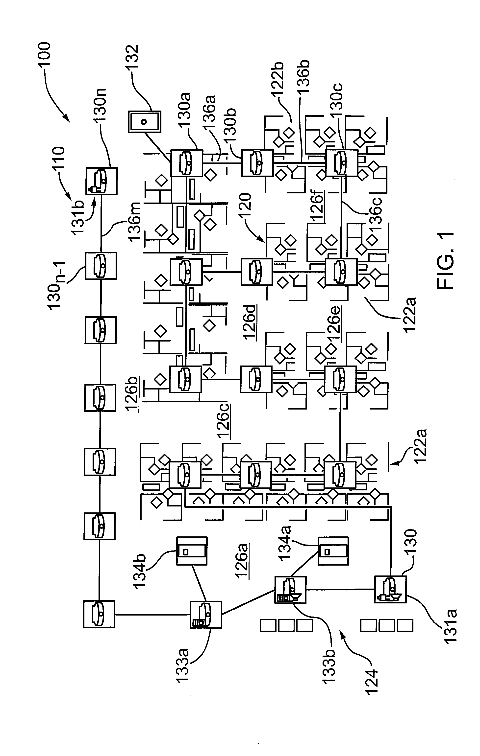
[0026]Reference is made to FIG. 1, which shows a sound masking configuration and control system according to an embodiment of the present invention and indicated generally by reference 100. The sound masking configuration and control system 100 comprises an active sound masking component layer 110 and an electronic design drawing 120. The electronic design drawing 120 comprises a floor plan or architectural drawing rendered in an electronic format for display on a computer display terminal. In the context of the present description, the design drawing 120 comprises a design drawing generated by the AUTOCAD™ software application.

[0027]As shown in FIG. 1, the design drawing 120 depicts an office space on a floor of a building. The office space comprises a number of workstation or cubicle groups 122, indicated individually by references 122a, 122b, . . . 122n, a main entrance and reception area 124, and corridors 126, indicated individually by references 126a, 126b, . . . 126f. In acco...


PUM


Abstract

A system and mechanism for monitoring and / or controlling a sound masking system from a computer aided design drawing. According to an embodiment, the system is configured to allow an operator to “click” sound masking components on the design drawing and view operating / configuration settings, and / or edit, change or modify the operating / configuration settings, which are then applied via an interface to the associated physical sound masking component in the sound masking system. According to another embodiment, the system is configured to allow an operator to design or configure sound masking components on a design drawing. The sound masking components correspond to physical sound masking components in a sound masking system and comprise one or more active sound masking elements, which are configured to be responsive to an input and allow an operator to monitor, change and / or modify operating / configuration settings for physical sound masking component via the sound masking element in the design drawing.

Description

FIELD OF THE INVENTION[0001]The present invention relates to sound masking systems and more particularly to a system and method for controlling and / or monitoring a sound masking system from an electronic floorplan or CAD drawing.BACKGROUND OF THE INVENTION[0002]Sound masking systems are widely used in offices and similar workplaces where an insufficient level of background sound results in diminished speech and conversational privacy. Such environments typically suffer from a high level of noise distractions, and lower comfort levels from an acoustic perspective. Sound masking systems operate on the principle of masking, which involves generating a background sound in a given area. The background sound has the effect of limiting the ability to hear two sounds of similar sound pressure level and frequency simultaneously. By generating and distributing the background noise in the given area, the sound masking system masks or covers the propagation of other sounds in the area and there...

Claims


Application Information

Patent Timeline
Patent Type & Authority Patents(United States)
IPC IPC(8): H04R3/02
CPCG10K11/175G06F3/162G06F17/5004G10K11/1752H04K3/42H04K3/43H04K3/825H04K2203/12H04K2203/34
Inventor MOELLER, NIKLASBABINEAU, PETER
Owner 777388 ONTARIO
Why Eureka
Try Eureka