Method of fabricating a nearwall nozzle impingement cooled component for an internal combustion engine

Inactive Publication Date: 2014-03-11
SIEMENS ENERGY INC
View PDF27 Cites 42 Cited by
  • Summary
  • Abstract
  • Description
  • Claims
  • Application Information

AI Technical Summary

Problems solved by technology

However, a desire to increase operating temperatures and other changes in turbine technology leave room for improvement in the art.

Method used


Image

  • Method of fabricating a nearwall nozzle impingement cooled component for an internal combustion engine
  • Method of fabricating a nearwall nozzle impingement cooled component for an internal combustion engine
  • Method of fabricating a nearwall nozzle impingement cooled component for an internal combustion engine

Examples


Embodiment Construction

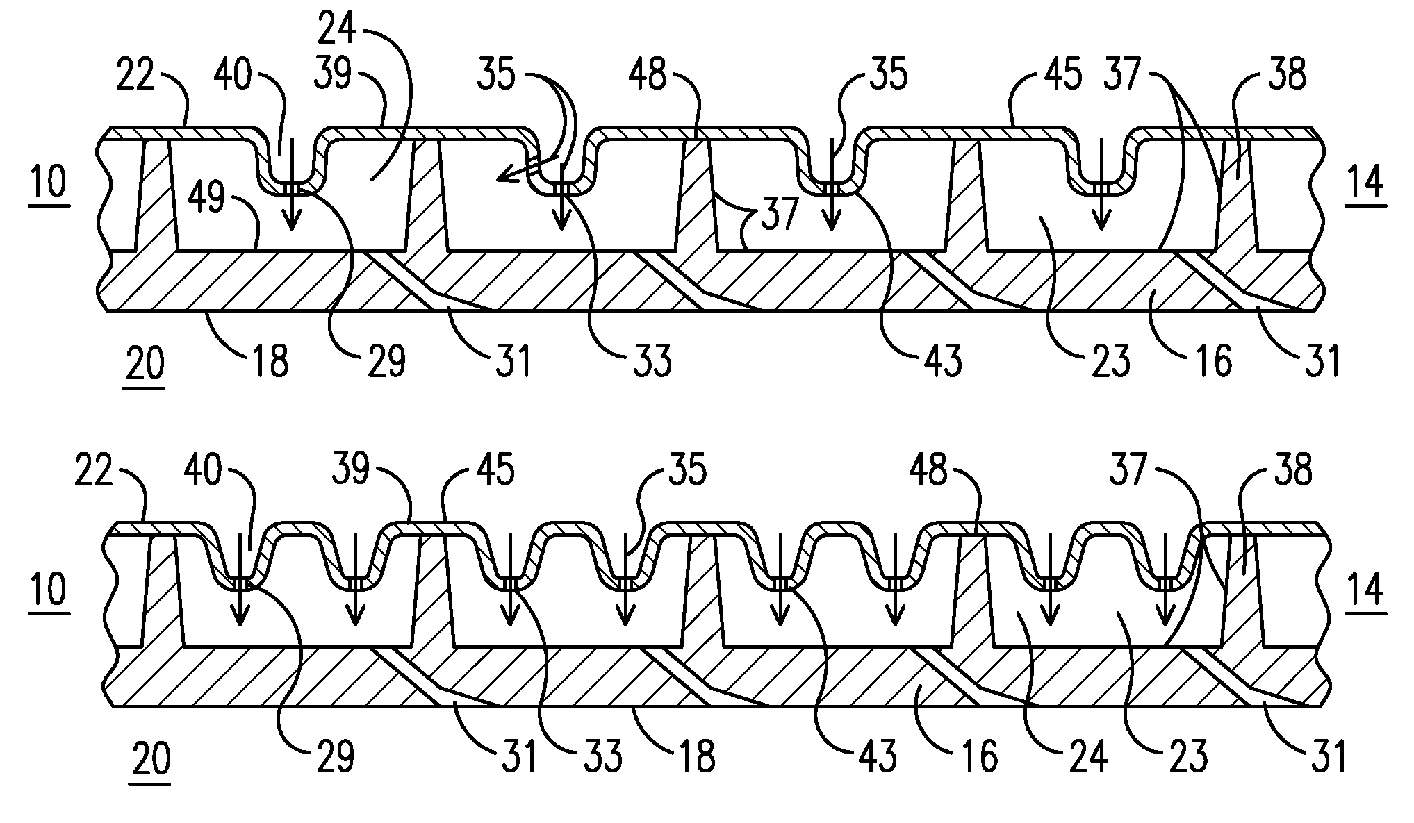
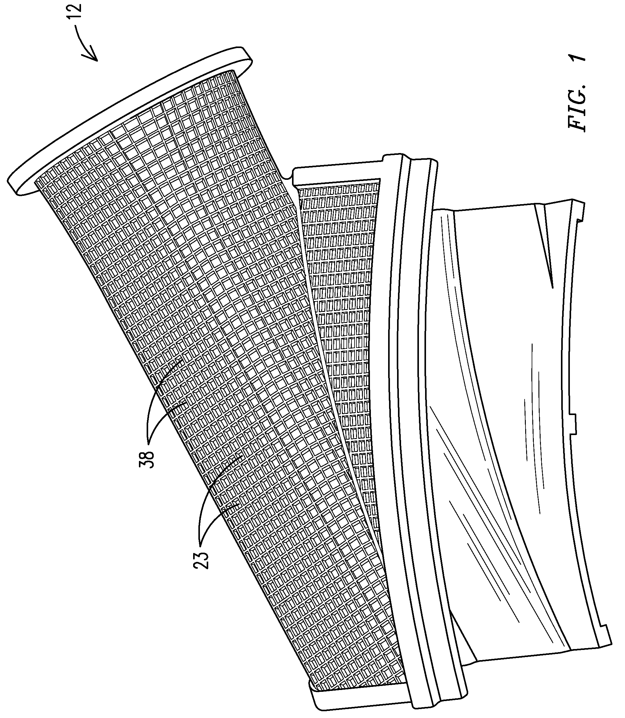
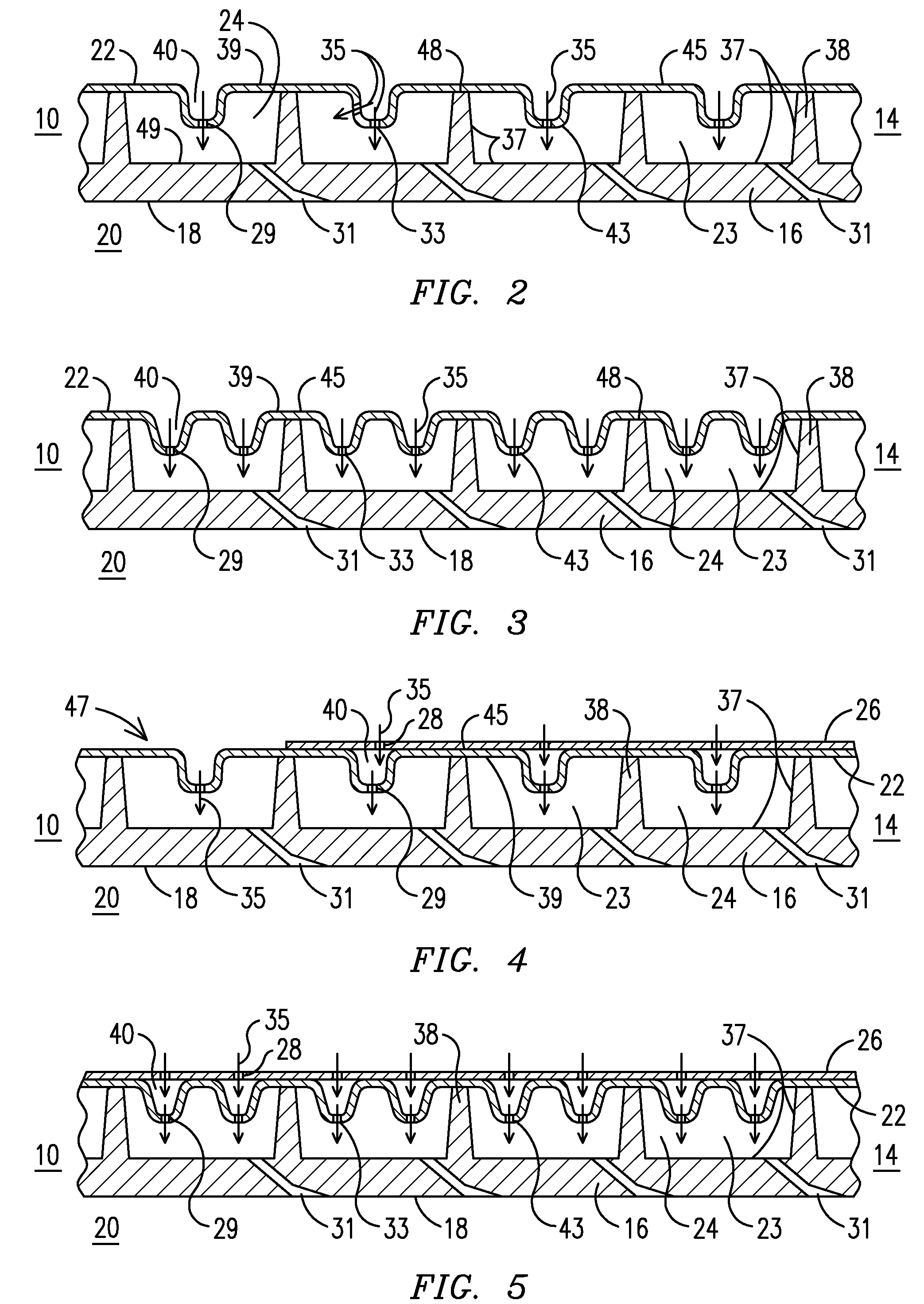
[0009]The inventors have devised an innovative, simple, inexpensive, and easy to manufacture method for forming a cooling system for an internal engine component exposed to a hot gas path. The cooling system may be configured for use with any component in contact with the hot gas path of an internal combustion engine, such as a component defining the hot gas path of a turbine engine. The method is useful for components that are used under high thermally stressed conditions and having complex outer surface contours. One such component is a transition duct, and others include vane platforms, ring segments (blade outer air seals), combustor liners, etc. The transition duct may be configured to route gas flow in a combustion turbine subsystem that includes a first stage blade array having a plurality of blades extending in a radial direction from a rotor assembly for rotation in a circumferential direction, said circumferential direction having a tangential direction component, an axis ...


PUM

PropertyMeasurementUnit
temperaturesaaaaaaaaaa
sizeaaaaaaaaaa
temperaturesaaaaaaaaaa

Abstract

A method of forming an internal combustion engine component having a multi-panel outer wall. The multi-panel outer wall has an inner panel (16) with an inner surface (18) and an outer surface (37). The inner panel outer surface (37) has discrete pockets (23) formed by integral structural ribs (38). Each pocket (23) has a film cooling hole (31) between the pocket (23) and the plenum (20). The method includes: forming dimples (40) in the intermediate panel (22), at least one dimple (40) having a nozzle (29); securing the intermediate panel (22) to the inner panel outer surface (37), thereby enclosing at least one pocket (23); and ensuring a respective dimple (40) having a nozzle (29) protrudes into a respective enclosed pocket (24) and a respective nozzle (29) is configured to direct a respective jet (35) of cooling fluid onto the inner panel outer surface within the respective enclosed pocket (23).

Description

FIELD OF THE INVENTION[0001]This invention is directed generally to internal combustion engines and, more particularly, to components useful for routing hot gasses. More specifically, the invention relates to methods of forming and assembling multi-panel walls having complex geometric contoured outer surfaces.BACKGROUND OF THE INVENTION[0002]Typically, gas turbine engines include a compressor for compressing air, a combustor for mixing the compressed air with fuel and igniting the mixture, and a turbine blade assembly for producing power. Combustors often operate at high temperatures that may exceed 2,500 degrees Fahrenheit. Typical turbine combustor configurations expose turbine components to these high temperatures. As a result, turbine components must be made of materials capable of withstanding such high temperatures. Turbine blades, vanes, transitions and other components often contain cooling systems for prolonging the life of these items and reducing the likelihood of failure...

Claims


Application Information

Patent Timeline
Patent Type & Authority Patents(United States)
IPC IPC(8): B21D53/00
CPCF05D2260/201B21K3/00F01D9/023F23R3/425F23R3/46Y10T29/49231Y10T29/49346
Inventor LEE, CHING-PANGMORRISON, JAY A.
Owner SIEMENS ENERGY INC
Why Eureka
Try Eureka