

Angle guide plate and system for securing a rail
a technology of securing rails and guide plates, which is applied in the direction of rail fasteners, railway track construction, and ways. it can solve the problems of affecting the proper positioning of rails, affecting the safety of rails, so as to avoid excessive wear, facilitate further movement of tension, and avoid the effect of excessive wear
- Summary
- Abstract
- Description
- Claims
- Application Information
AI Technical Summary
Benefits of technology
Problems solved by technology
Method used
Image

Examples
Embodiment Construction
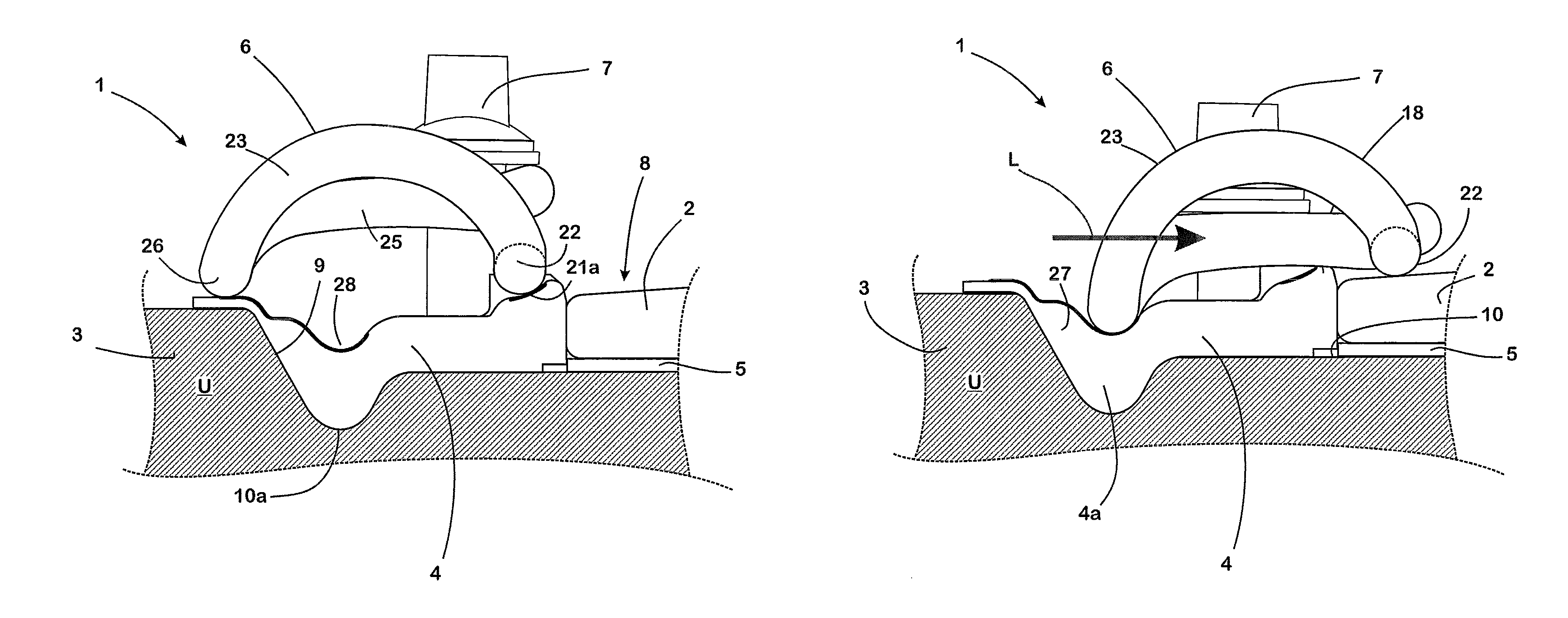
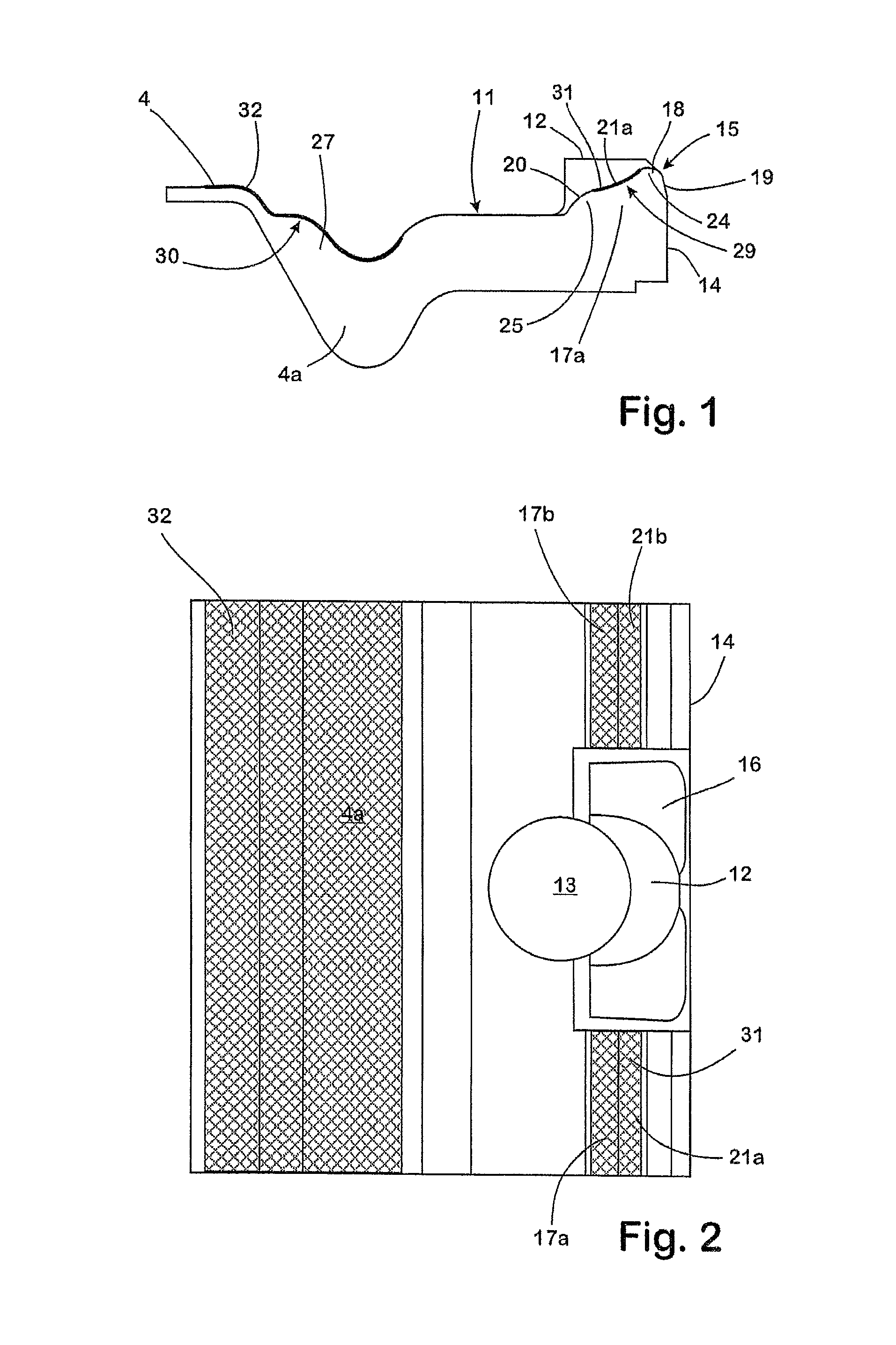
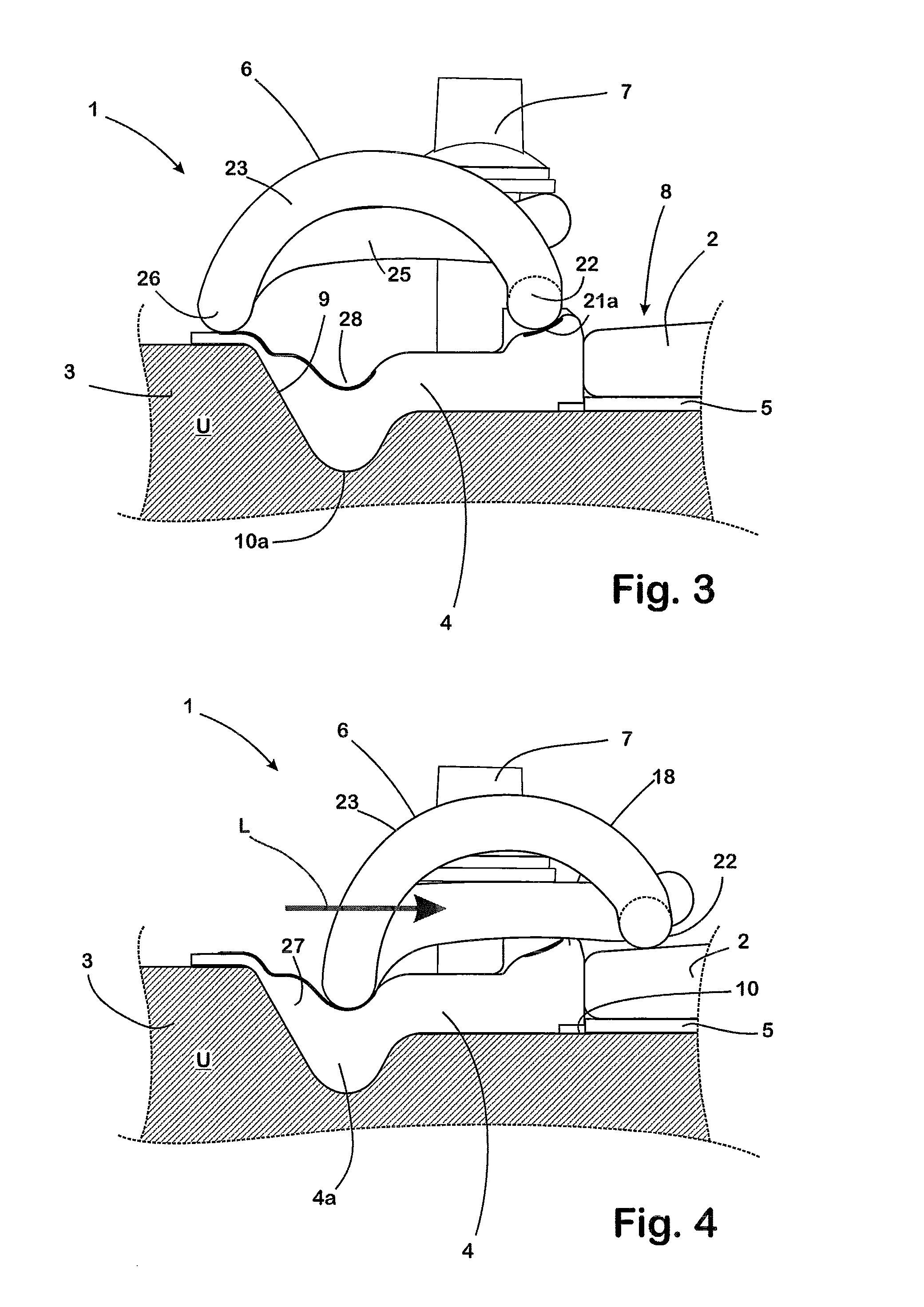
[0031]The system 1 shown in FIGS. 3 and 4 is used to secure a rail on a fixed foundation U, which in the present example, for the sake of easy overview, is formed from a concrete Sleeper 3 depicted only incompletely. For the same reason, with regard to the rail to be secured, only the edge area of the rail foot 2 facing the system 1 is represented in FIGS. 3 and 4.
[0032]The system 1 comprises an angle guide plate 4, an elastic layer 5, a W-shaped tension clamp 6, provided in order to produce the retaining force required, and a tension screw 7 serving as tensioning means for tensioning the tension clamp 6.
[0033]The elastic layer 5 consists of a fine-porous highly elastic polyurethane foam, the elasticity of which is provided in such a way that, even if suddenly relieved of pressure after an extended period of full compression, it will immediately relax automatically and expand again up to the initial thickness of the elastic layer 5.
[0034]A recess 8 is formed into the concrete sleepe...
PUM
 Abstract
Description
Claims
Application Information