Shallow flat soffit precast concrete floor system

a precast concrete and flat soffit technology, applied in the direction of joists, girders, constructions, etc., can solve the problems of reducing the clear floor height, reducing the construction speed, and reducing the cost of time and labor, so as to reduce the floor height, maintain the construction speed, and save the cost of mechanical and electrical equipment. , the effect of saving the cost of building

Active Publication Date: 2014-03-18
BOARD OF RGT UNIV OF NEBRASKA
View PDF12 Cites 12 Cited by
  • Summary
  • Abstract
  • Description
  • Claims
  • Application Information

AI Technical Summary

Benefits of technology

[0015]The present invention provides a flat soffit shallow precast floor system for multi-story residential and office buildings. The system minimizes the limitations of existing precast floor systems with regard to span-to-depth ratio and floor projections, while maintaining speed of construction, simplicity, and economy. More specifically, the present system has a span-to-depth ratio of at least 30 to reduce the floor height and save in architecture, mechanical, and electrical costs. In addition, the present system eliminates the column corbels and beam ledges to provide additional space and flat soffit for residential and office buildings. Further, it consists of easy-to-produce and erect precast / prestressed components with minimal cast-in-place operations to ensure practicality, economy, quality, and speed of construction.

Problems solved by technology

The only option for constructing flat soffit shallow floors in multi-story buildings is using post-tensioned cast-in-place concrete flat slab, which is complicated, costly, and time-consuming.
Current precast concrete floor systems require the use of beam ledges to support hollow core planks and column corbels to support beams, which result in projections that further reduce the clear floor height in addition to the already low span-to-depth ratio.
1. All proposed ledge-less hollow-core-beam connections (shear key and hidden ledge with and without angles) performed very well as their shear capacity exceeded the predicted values and significantly exceeded the demand. None of these connections has failed as the tested hollow-core planks failed in shear prior to the failure of the connections
2. The capacity of the proposed ledge-less hollow-core-beam connections can be accurately predicted using shear friction theory.
3. Since the shear capacity of the hollow-core-beam connections without steel angle was adequate, steel angles are considered as temporary ledges that do not affect the fire rating of the building

Method used


Image

  • Shallow flat soffit precast concrete floor system
  • Shallow flat soffit precast concrete floor system
  • Shallow flat soffit precast concrete floor system

Examples


example 1

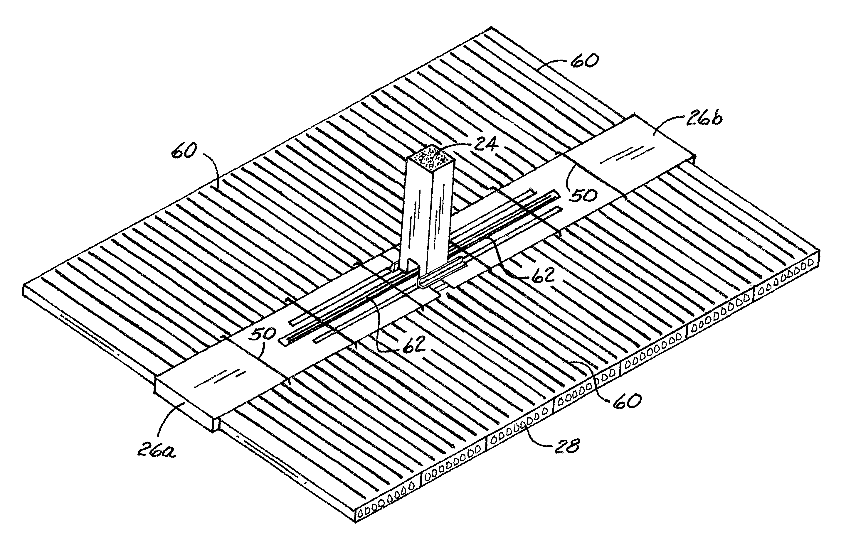
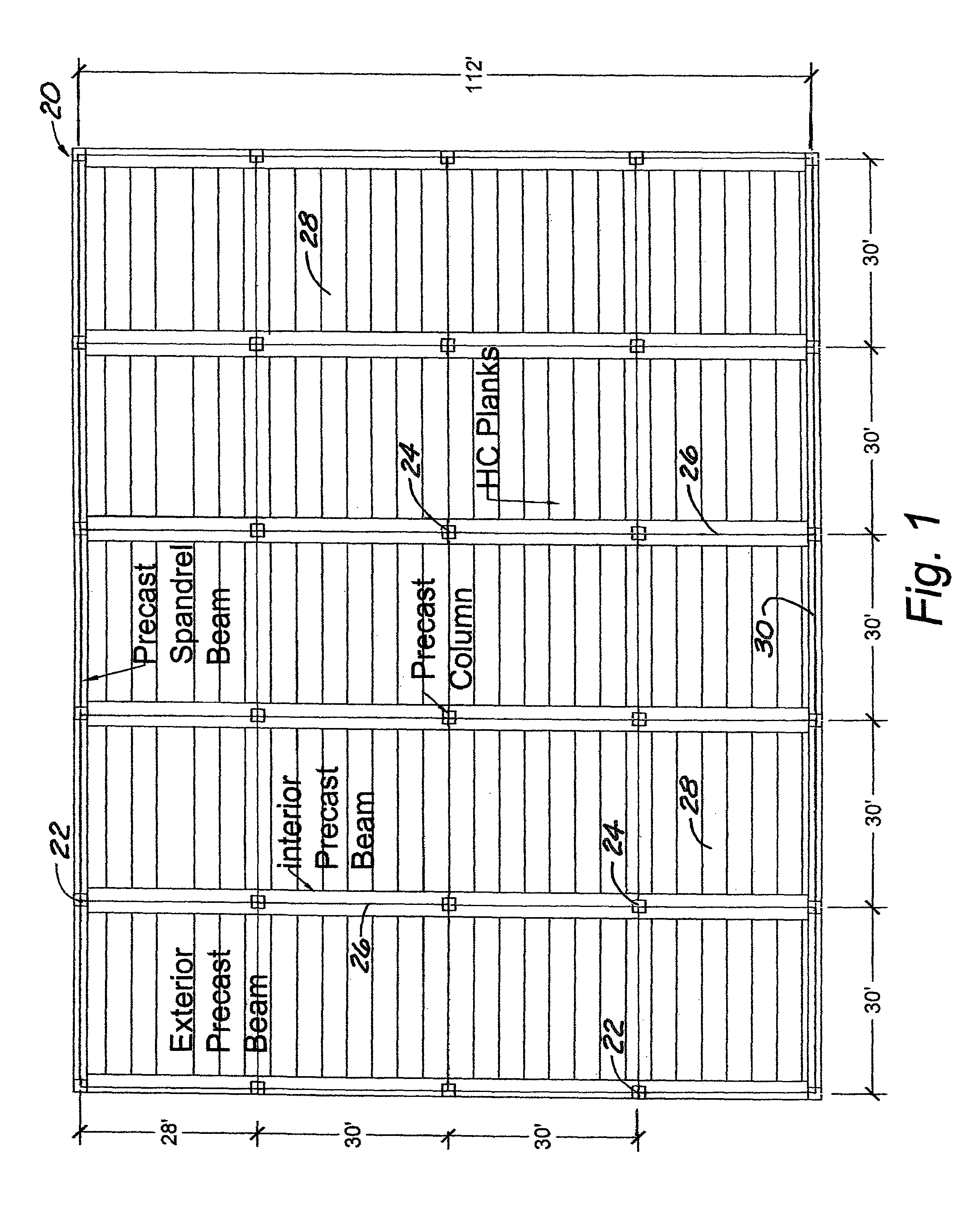
[0051]Referring to the figures, there is depicted in FIG. 1, generally at 20, a layout of a floor of a sample or exemplary building constructed using the components and systems of the present invention. The layout 20 includes twenty 30 foot bays in a 4×5 bay arrangement. Also included are eighteen precast exterior columns 22 and twelve precast interior columns 24. Beams 26 are supported on the columns and floor support member hollow-core planks 28 are supported on the beams 26. Spandrel beams 30 are supported on and between adjacent precast exterior columns 22.

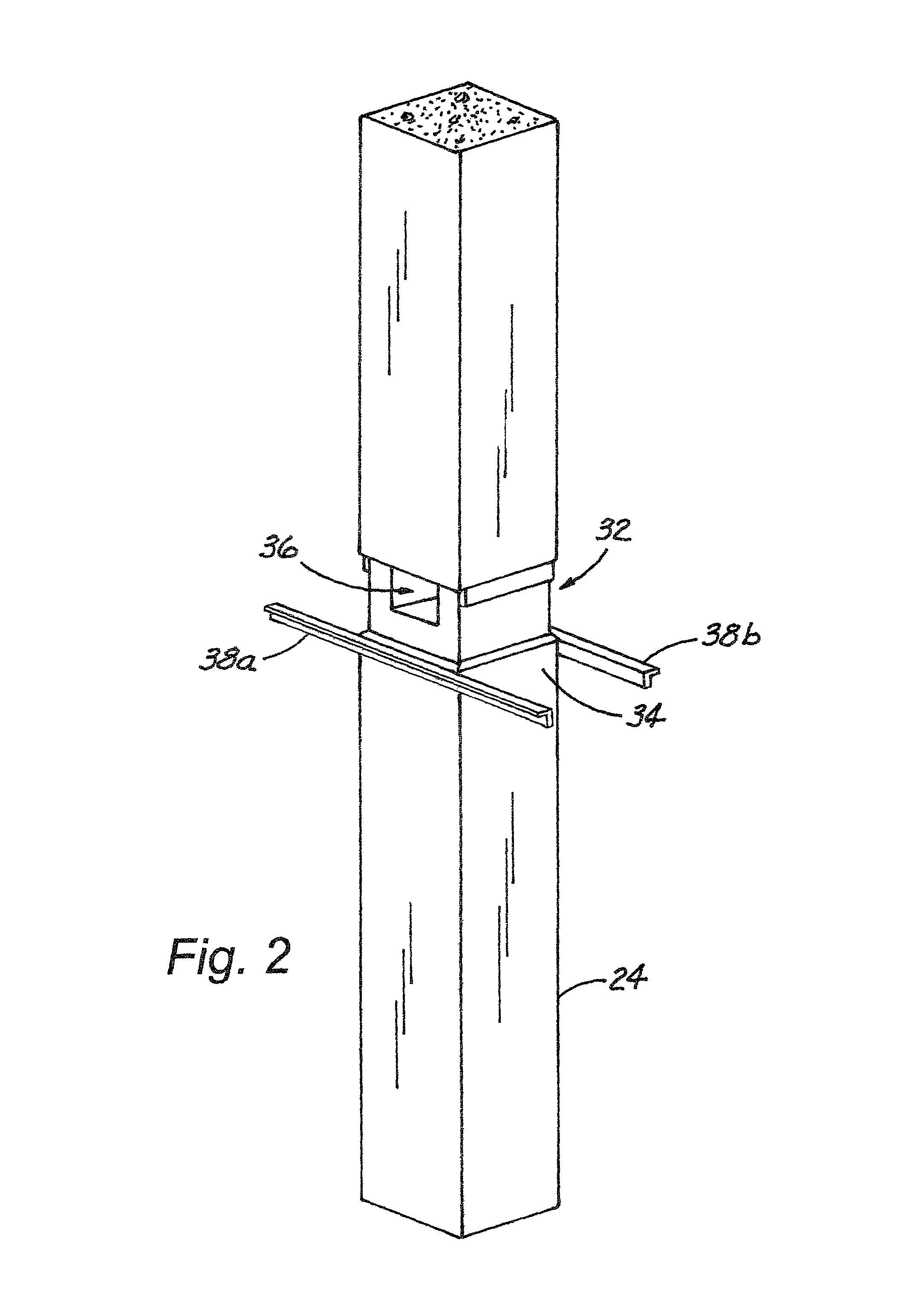
[0052]The precast interior columns 24 have a reduced width section, generally at 32 (FIG. 2) which forms a ledge 34 around the column 24 at the height where the floor is to be installed. In addition, an opening 36 is formed in the column 24 in the reduced width section 32. Temporary corbels 38a and 38b have been attached to the column 24 on the ledge 34 on either side of the opening 36. The temporary corbels 38 will most typic...

example 2

[0059]The experimental investigation presented was carried out to evaluate the shear capacity of four different hollow-core-beam connections as well as the flexural capacity of the shallow rectangular beam. The shear capacity of beam-column connection (i.e., hidden corbel) was evaluated in an earlier investigation (Morcous and Tadros, 2011). The full-scale test specimen shown in FIG. 13 consists of a 28 ft long, 10 inch thick, and 48 inch wide precast rectangular beam 26 and twelve 6 ft long, 10 inch thick, and 48 inch wide hollow-core plank 28 segments. In the shown test setup, the beam 26 was supported by three roller supports (i.e. two end supports and one middle support) to minimize beam deflection while testing the capacity of hollow-core-beam connections. The beam 26 was fabricated with two different alternatives of ledge-less hollow-core connections, shear key and hidden ledge. For each alternative, two temporary ledges were used to support hollow-core planks during construct...


PUM


Abstract

A precast concrete floor system that eliminates the need for column corbels and beam ledges while being very shallow. The main advantages of the present system include a span-to-depth ratio of 30, a flat soffit, economy, consistency with prevailing erection techniques, and fire and corrosion protection. The present system consists of continuous precast columns, prestressed rectangular beams, hollow-core planks, and cast-in-place composite topping. Testing results have indicated that a 12 inch deep flat soffit precast floor system has adequate capacity to carry gravity loads (including 100 psf live load) in a 30 ft×30 ft bay size. Testing has also shown that shear capacity of the ledge-less hollow-core-beam connections can be accurately predicted using the shear friction theory.

Description

CROSS-REFERENCE TO RELATED APPLICATIONS[0001]This application claims priority to U.S. Patent Application Ser. No. 61 / 468,642, filed Mar. 29, 2011, which is incorporated herein in its entirety by this reference.BACKGROUND OF THE INVENTION[0002]The present invention relates generally to precast concrete floor systems and, more specifically, to a precast concrete floor system that has a shallow flat soffit and uses no corbels to reduce the floor height while maximizing useable space.[0003]Conventional hollow-core floor systems consist of hollow-core planks supported by inverted-tee (IT) precast prestressed concrete beams, which are, in turn, supported on column corbels or wall ledges. These floor systems provide a rapidly constructed solution to multi-story buildings that is economical, fire-resistant, and with excellent deflection and vibration characteristics. The top surface of hollow-core floor systems can be a thin non-structural cementitious topping or at least 2 inch thick concr...

Claims


Application Information

Patent Timeline
Patent Type & Authority Patents(United States)
IPC IPC(8): E04B1/00
CPCE04B5/265E04B5/043E04B5/43E04B5/16E04C3/20E04B1/04
Inventor MORCOUS, GEORGETADROS, MAHER
Owner BOARD OF RGT UNIV OF NEBRASKA
Why Eureka
Try Eureka