High pressure vessel with integrated mounting features

a technology of high-pressure vessels and mounting features, which is applied in the field of mounting systems, can solve the problems of inefficient use of package space, small diameter to length ratio of pressure vessels, and large size, and achieve the effect of minimizing system mass and large diameter

Inactive Publication Date: 2014-03-18
GM GLOBAL TECH OPERATIONS LLC
View PDF6 Cites 1 Cited by
  • Summary
  • Abstract
  • Description
  • Claims
  • Application Information

AI Technical Summary

Benefits of technology

[0007]Presently provided by the invention, a mounting system that permits a repeated expansion and contraction of the pressure vessel, restrains the vessel having a large diameter to length ratio, and minimizes mass of the system into which the pressure vessel is incorporated, has surprisingly been discovered.

Problems solved by technology

The conventional restraining means (typically including a plurality of circumferential bands fastened to a support structure) may be of considerable size and restrict service of the pressure vessels.
The pressure vessel having a small diameter to length ratio makes inefficient use of the package space and facilitates the use of conventional restraining means.
As a result, the cost and the mass of the fuel cell system including the plurality of the pressure vessels may become undesirably high.

Method used


Image

  • High pressure vessel with integrated mounting features
  • High pressure vessel with integrated mounting features
  • High pressure vessel with integrated mounting features

Examples


Embodiment Construction

[0015]The following detailed description and appended drawings describe and illustrate various embodiments of the invention. The description and drawings serve to enable one skilled in the art to make and use the invention, and are not intended to limit the scope of the invention in any manner.

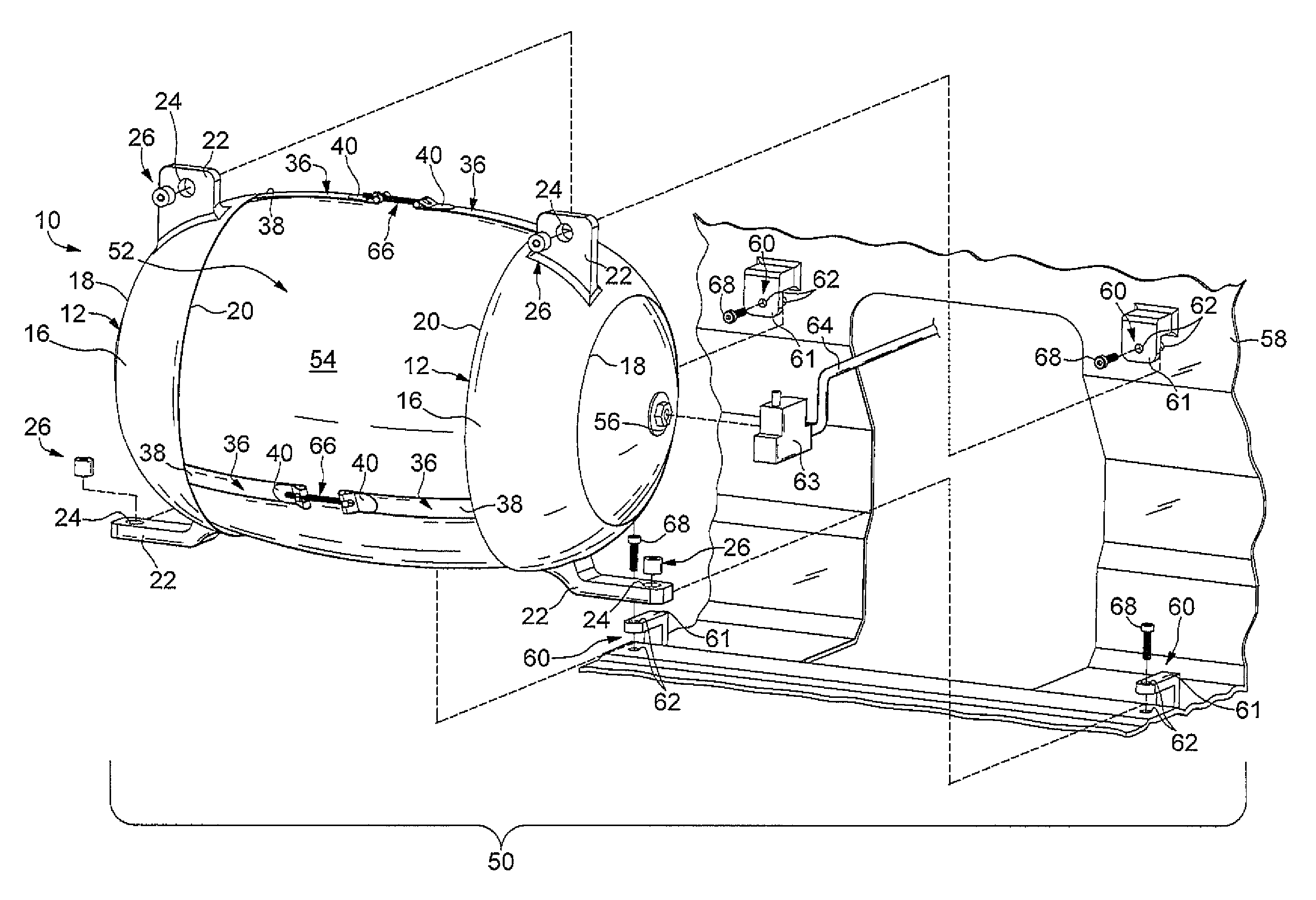
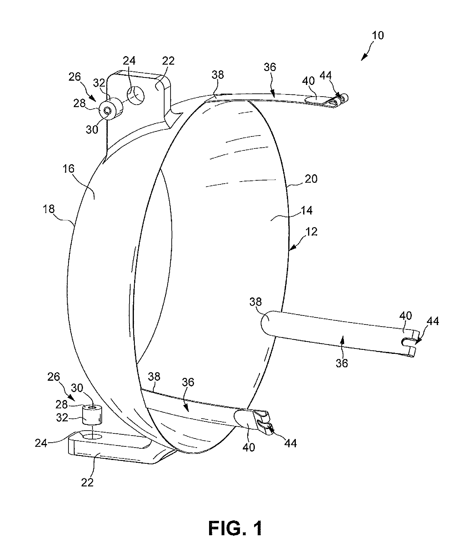
[0016]FIG. 1 illustrates a mounting system 10 including a retention cap 12 according to an embodiment of the present invention. The retention cap 12 is typically formed from steel, but other materials such as aluminum, magnesium, other metals, or a composite material may be used. As illustrated, the retention cap 12 is a truncated hollow conoid, but other shapes such as a hollow hemisphere or a hollow prism may be used. The retention cap 12 has a concave inner surface 14 and an outer surface 16. A thickness of the retention cap 12 separating the concave inner surface 14 and the outer surface 16 is substantially constant, but the thickness may vary in other embodiments. The retention cap 12 inc...


PUM

PropertyMeasurementUnit
viscoelasticaaaaaaaaaa
thicknessaaaaaaaaaa
resilientaaaaaaaaaa

Abstract

A mounting system for a pressure vessel is disclosed. The mounting system includes a first retention cap, a second retention cap, and a plurality of fastening bands coupled to the first retention cap and the second retention cap, wherein the first retention cap and the second retention cap each include a concave inner surface and a mount, the concave inner surface substantially corresponding to at least a portion of an exterior surface of the pressure vessel to secure the pressure vessel between the first retention cap and the second retention cap.

Description

FIELD OF THE INVENTION[0001]The invention relates to pressure vessels, and more particularly to a mounting system for a pressure vessel including a retention cap and a fastening band.BACKGROUND OF THE INVENTION[0002]Fuel cells have been proposed as a power source for electric vehicles and other applications. In proton exchange membrane (PEM) type fuel cells, hydrogen is supplied as a fuel to an anode of the fuel cell and oxygen is supplied as an oxidant to a cathode of the fuel cell. A plurality of fuel cells is stacked together in fuel cell stacks to form a fuel cell system. The fuel is typically stored in large, hollow, substantially cylindrical pressure vessels disposed on an undercarriage of the vehicle.[0003]The pressure vessels are typically multi-layered and include at least an inner liner and a filament wound outer shell. The pressure vessels may expand or contract when a pressure and a temperature of the fuel within the vessels changes. A restraining means disposed on the p...

Claims


Application Information

Patent Timeline
Patent Type & Authority Patents(United States)
IPC IPC(8): B65D88/50
CPCF17C2203/012Y02E60/50F17C2203/0329F17C2205/0192H01M2250/20F17C2270/0184F17C2209/2154F17C2260/012F17C2203/0663F17C2209/227H01M8/04201F17C2201/056F17C2203/0604Y02T90/32F17C2201/0128F17C2205/0311F17C2203/0607F17C2201/035Y02T90/40
Inventor OELERICH, WOLFGANGSTEWART, BRYAN J.SHABANA, MOHSEN D.
Owner GM GLOBAL TECH OPERATIONS LLC
Why Eureka
Try Eureka