
Dialysis machine, in particular peritoneal dialysis machine

a dialysis machine and peritoneal technology, applied in the field of dialysis machines, can solve the problems of substantial risks for patients, difficult use of conductivity sensors, and often difficult sterilization of heated solutions in mixed state, and achieve the effect of reducing patient risks

Active Publication Date: 2014-03-18
FRESENIUS MEDICAL CARE DEUTSCHLAND GMBH
View PDF13 Cites 38 Cited by
  • Summary
  • Abstract
  • Description
  • Claims
  • Application Information

AI Technical Summary

Benefits of technology

The present invention reduces the risks for patients by providing a dialysis machine that uses a multi-chamber container with a partition arrangement that has to be opened mechanically. To minimize these risks, the dialysis machine automatically checks the proper opening of the partition arrangement using a sensor in the machine that determines a measured variable in the fluid system. This automatic checking allows for the use of the benefits of a multi-chamber container without the associated risks. The automatic checking can also check the proper mixing of the individual solutions, which reduces the risk of complications. The invention uses an optical property that changes by mixing with a second individual solution, which can be determined without the need for visibly dying the solution.

Problems solved by technology

This is due, on the one hand, to the fact that certain ingredients are incompatible for storage and unwanted waste products arise on storage in the mixed state.
In addition, the heat sterilization of the solution in the mixed state is often problematic or not possible.
This can result in substantial risks for the patient since hereby the correct dialysis fluid, which comprises a mixture of the plurality of individual solutions, is not used, but rather an individual solution.
The use of conductivity sensors is therefore extremely problematic in the field of peritoneal dialysis.
However, it has not yet been possible to achieve sufficient safety with known systems.

Method used


Image

  • Dialysis machine, in particular peritoneal dialysis machine
  • Dialysis machine, in particular peritoneal dialysis machine
  • Dialysis machine, in particular peritoneal dialysis machine

Examples


first embodiment

[0131]a cassette is shown in FIGS. 4a and 4b. It has a hard part 101 of plastic in which the fluid paths and coupling regions are introduced as corresponding cut-outs, chambers and passages. The hard part can in this respect be produced e.g. as an injection molded part or as deep drawn part. The coupling plane of the hard part 101 is covered by a flexible film 102 which is welded to the hard part in a marginal region. The flexible film 102 is pressed with the hard part by the pressing of the cassette with a coupling surface of the dialysis machine. The fluid paths within the cassette are separated from one another in a fluid tight manner by the pressing of the flexible film with the web regions of the hard part.

[0132]The cassette has connections for the connection of the cassette to the other fluid paths. On the one hand, a connection 21 is provided for the connection to the outflow 20 as well as a connection 31 for the connection to the connector 30. Corresponding hose elements whi...

second embodiment

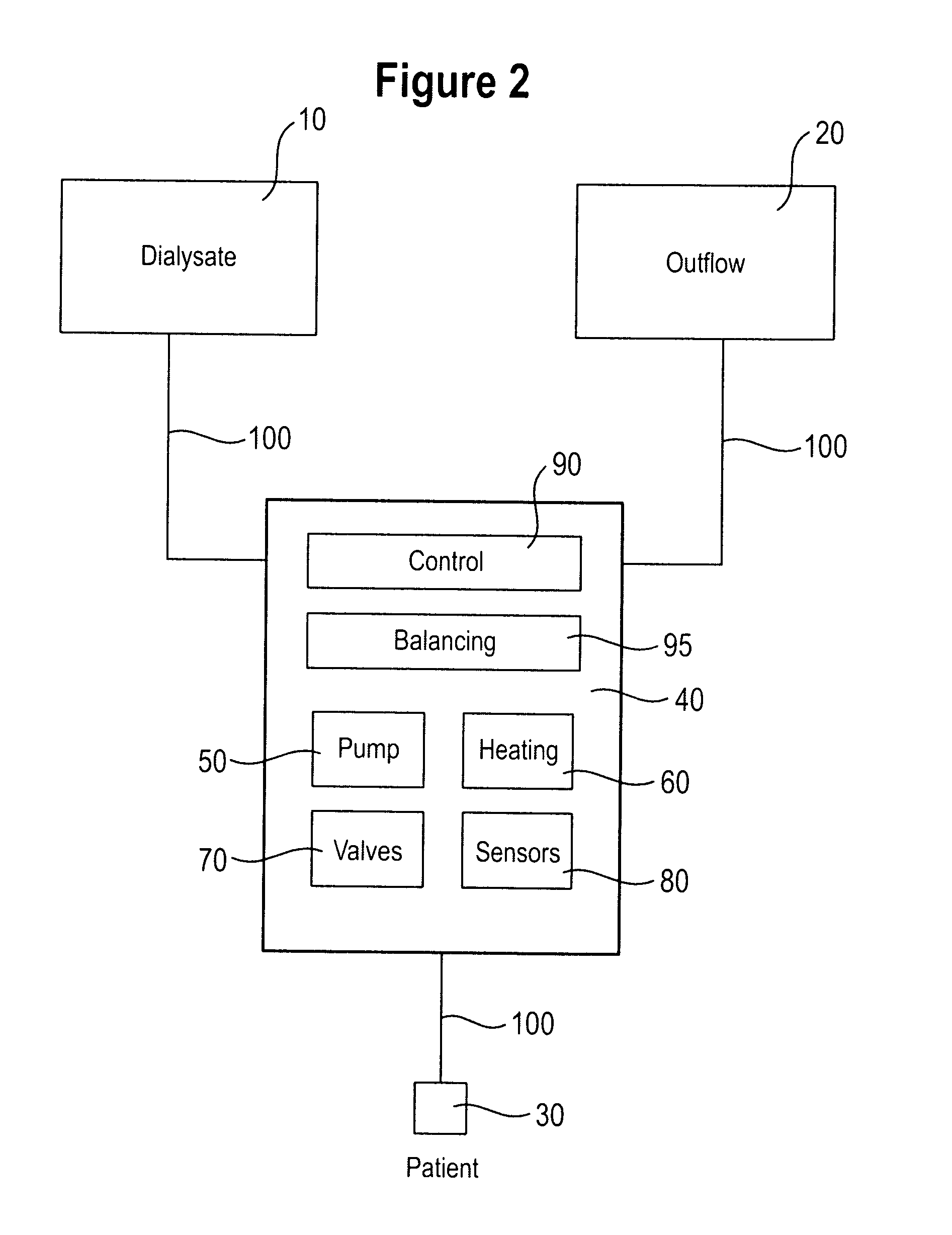
[0140]a cassette shown in FIG. 5 in turn has fluid paths which can be opened and closed via valve regions which are here likewise numbered consecutively from V1 to V16. The cassette furthermore has connections for the connection to further components of the fluid system. In this respect, the connection 21 is in turn provided for the connection to the outflow 20 and the connection 31 for connection to the connector 30 to the patient. Connections 11 are furthermore provided for the connection of dialysate containers 10.

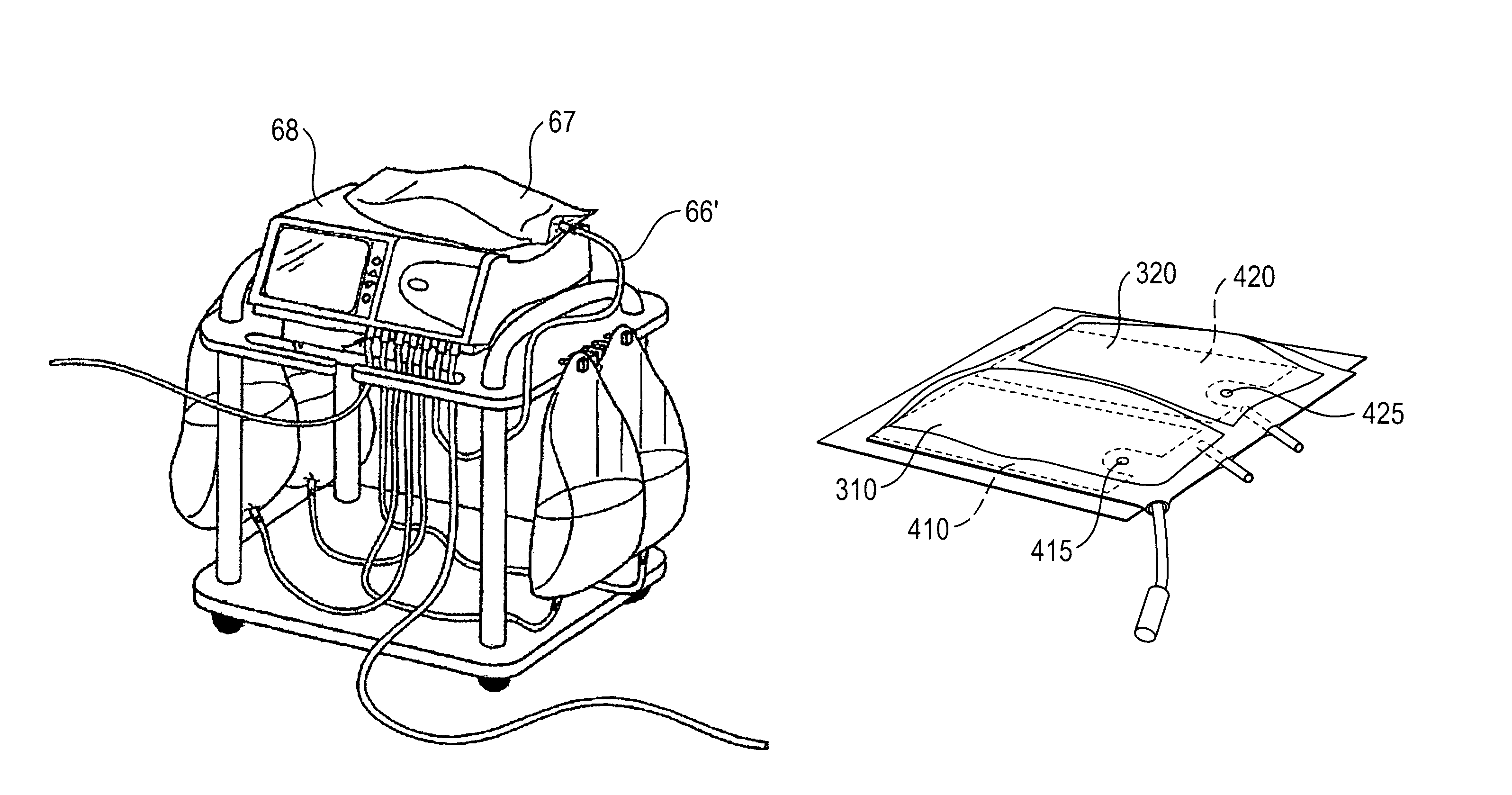
[0141]Unlike the first embodiment, the cassette shown in the second embodiment has a further connection 66 for the connection of a heating bag. In this respect, the liquid can be pumped into a heating bag via the connection 66 for the heating of the fluid from the dialysate containers 10. This heating bag lies on a heating element so that the fluid present in the heating bag can be heated. The fluid is thereupon pumped from the heating bag to the patient.

[0142]The pump ...


PUM

PropertyMeasurementUnit
Temperatureaaaaaaaaaa
Pressureaaaaaaaaaa
Flow rateaaaaaaaaaa

Abstract

A dialysis machine, in particular a peritoneal dialysis machine, to which a fluid system having a multi-chamber container with at least two chambers with individual solutions separated by a partition arrangement to be opened mechanically can be coupled includes a controller and at least one sensor for the determination of a measured variable in the fluid system. The controller has an apparatus for the automatic checking of the proper opening of the partition arrangement with reference to the measured variable determined by the sensor.

Description

[0001]This application has a priority of German no. 10 2009 060 330.1 filed Dec. 23, 2009, hereby incorporated by reference.BACKGROUND OF THE INVENTION[0002]1. Field of Invention[0003]The present invention relates to a dialysis machine, in particular a peritoneal dialysis machine, to which a fluid system can be coupled which has a multi-chamber container with at least two chambers comprising individual solutions and separated by a partition arrangement to be opened mechanically. The dialysis machine in this respect furthermore has a controller and at least one sensor for the determination of a measured variable in the fluid system.[0004]2. Description of the Prior Art[0005]In the field of dialysis, in particular in the field of peritoneal dialysis, it is usual to mix prepared individual solutions with one another only briefly before the treatment in order thus to provide a finished dialysis solution. This is due, on the one hand, to the fact that certain ingredients are incompatible...

Claims


Application Information

Patent Timeline
IPC IPC(8): B01D61/32B01D61/28B01D61/24
CPCA61M1/1656A61J1/2093A61M1/287A61M1/282A61M1/1668A61M1/166A61M1/167A61M1/1617A61M1/1565A61M1/159A61M1/1524A61M1/155A61M1/153A61M1/1561A61M1/154
Inventor HEDMANN, FRANKSEBESTA, SVEN
Owner FRESENIUS MEDICAL CARE DEUTSCHLAND GMBH
Learn More