Beam monitor system and particle beam irradiation system

a monitor system and beam technology, applied in the field of beam monitor system and particle beam irradiation system, can solve the problems of large scale of bean monitoring system alone, long time it takes to detect the position of charged particle beam, and large beam width, and achieve the effect of simple configuration

Active Publication Date: 2014-03-18
HITACHI LTD
View PDF3 Cites 3 Cited by
  • Summary
  • Abstract
  • Description
  • Claims
  • Application Information

AI Technical Summary

Benefits of technology

[0010]It is therefore an object of the invention to provide a bean monitoring system, and a charged particle beam irradiation system, capable of monitoring a position passed by a charged particle beam, and a beam width thereof, in a simple configuration, and making a determination in short time during spot irradiation according to the scanning method.
[0012]According to the present embodiment, channels for use in working, out a position of the charged particle beam, and a beam width are restricted, so that it is possible to construct a monitor system simple in configuration as compared with a monitor system provided with a signal processor corresponding to all the channels.

Problems solved by technology

In order to find the position passed by the charged particle beam, and the beam width, it is necessary to execute signal amplification, and signal processing with respect to all the channels, so that there arises a problem that the further the number of the channels is increased, the longer it takes in order to detect the position of the charged particle beam, and the beam width.
However, in the case of the method for measuring the charged particle beam, described as above, if a multitude of channels are required, the bean-monitoring system alone will become large in scale, and complex in configuration for the reasons of irradiation applied with a fine beam, and so forth, and therefore, a cost becomes high.

Method used


Image

  • Beam monitor system and particle beam irradiation system
  • Beam monitor system and particle beam irradiation system
  • Beam monitor system and particle beam irradiation system

Examples


first embodiment

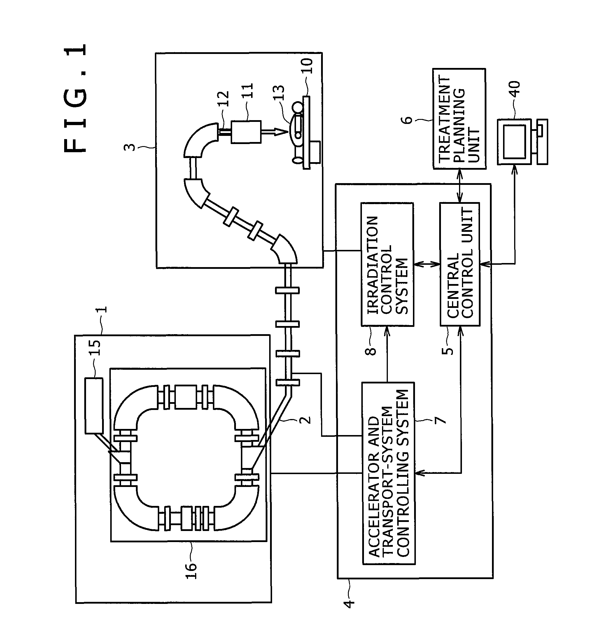
[0023]A preferred embodiment of a particle beam irradiation system according to the invention is described hereinafter with reference to FIGS. 1 and 2. The particle beam irradiation system is a system for irradiating an affected part of a patient fixed on a treatment table (a bed) 10 inside a treatment room with a charged particle beam 12 (for example, a proton beam, a carbon beam, and so forth).

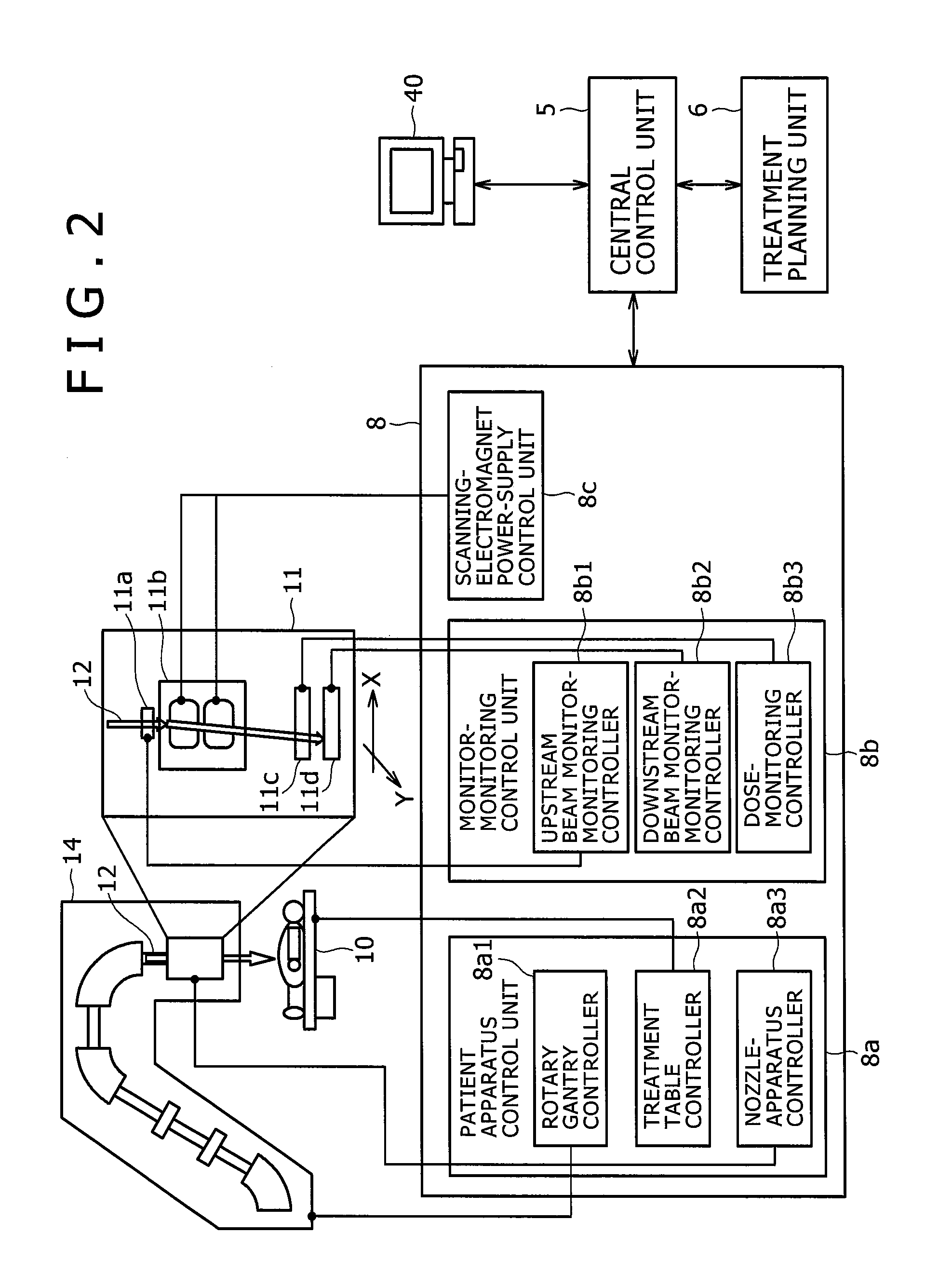
[0024]The particle beam irradiation system according to the present embodiment is provided with a charged particle beam generation unit 1, a beam transport system 2, a scanning irradiation unit 3, and a control system 4. The beam transport system 2 connects the charged particle beam generation unit 1 to the scanning irradiation unit 3. The control system 4 is connected to a treatment planning unit 6, and an operation terminal 40, respectively. The operation terminal 40 is provided with an input device where an operator (a treatment worker) inputs data, and an instruction signal, and a displa...

second embodiment

[0060]There is described hereinafter a particle beam irradiation system according to another embodiment of the invention with reference to FIG. 8. With the particle beam irradiation system according to the first embodiment, the beam monitor system has the configuration whereby the two segments are organized into the one group, however, the particle beam irradiation system according to a second embodiment includes a beam monitor system whereby a plurality of segments are organized into one group. There is described hereinafter a configuration of the beam monitor system according to the present embodiment, differing from the case of the first embodiment.

[0061]The beam monitor system according to the present embodiment represents the case of a beam monitor system where group numbers are N-groups, and the number of the channels in the segment is Lch. Assuming that a beam distribution necessary for calculation of a beam position, and a beam width is to appear in (M−1) segment, the number...

third embodiment

[0066]There is described hereinafter a particle beam irradiation system according to a third embodiment of the invention with reference to FIG. 9. In contrast to the first embodiment relating to the particle beam irradiation system provided with the beam monitor system for monitoring the beam position, and the beam width in execution of the spot-scanning irradiation method, the particle beam irradiation system according to the present embodiment is provided with a beam monitor system for monitoring a beam position, and a beam width in execution of a raster scanning irradiation method. The particle beam irradiation system according to the present embodiment is provided with the beam monitor system for monitoring the beam position, and the beam width in execution of the raster scanning irradiation method whereby an affected part of a patient 13 is divided into a plurality of layers in the travelling direction of the charged particle beam, thereby scanning with the charged particle bea...


PUM


Abstract

Disclosed is a beam monitor system in which signals outputted from a plurality of wires are divided in a multi-wire type monitor for measuring a beam profile of a charged particle beam, an identical number of the wires are grouped, the signals of the respective groups are taken out one piece by one piece to be connected with each other, and the number of the pieces, corresponding to a number of the wires belonging to the one group, are put together to be connected to a signal processor storing connection information.

Description

FIELD OF THE INVENTION[0001]The present invention relates to a method for monitoring a beam position in a charged particle beam irradiation system, and controlling the beam position, and in particular, to a charged particle beam irradiation system suitable for application to a charged particle beam treatment apparatus for giving treatment to an affected part by irradiating the affected part with a beam of a charged particle such as a proton, a carbon ion, and so forth.BACKGROUND OF THE INVENTION[0002]There has been known a treatment method whereby an affected part of a patient of cancer, and so forth is irradiated with a charged particle beam (an ion beam) of a proton, a carbon ion, and so forth. A charged particle beam irradiation system (a particle beam emitting apparatus, or a charged particle beam emitting apparatus) for use in this treatment is provided with a charged particle beam generation unit, and a charged particle beam accelerated by the charged particle beam generation ...

Claims


Application Information

Patent Timeline
Patent Type & Authority Patents(United States)
IPC IPC(8): G21K5/04
CPCA61N2005/1087A61N5/1075A61N5/1071G01T1/29A61N2005/1074A61N5/1043G01T1/2935A61N5/1048
Inventor IWAMOTO, TOMOHISAHORI, YOSHIHITOMATSUSHITA, TAKAYOSHIMORIYAMA, KUNIOTADOKORO, MASAHIRO
Owner HITACHI LTD
Why Eureka
Try Eureka