

Apparatuses and methods for energy storage
a technology of energy storage and apparatus, applied in the direction of electrical storage system, electric generator control, machines/engines, etc., can solve the problems of alternating current of the electricity grid, deviation from the target operating condition, and the lack of storage means of the electric power grid, so as to achieve stable operation of the electrical grid
- Summary
- Abstract
- Description
- Claims
- Application Information
AI Technical Summary
Benefits of technology
Problems solved by technology
Method used
Image

Examples
Embodiment Construction
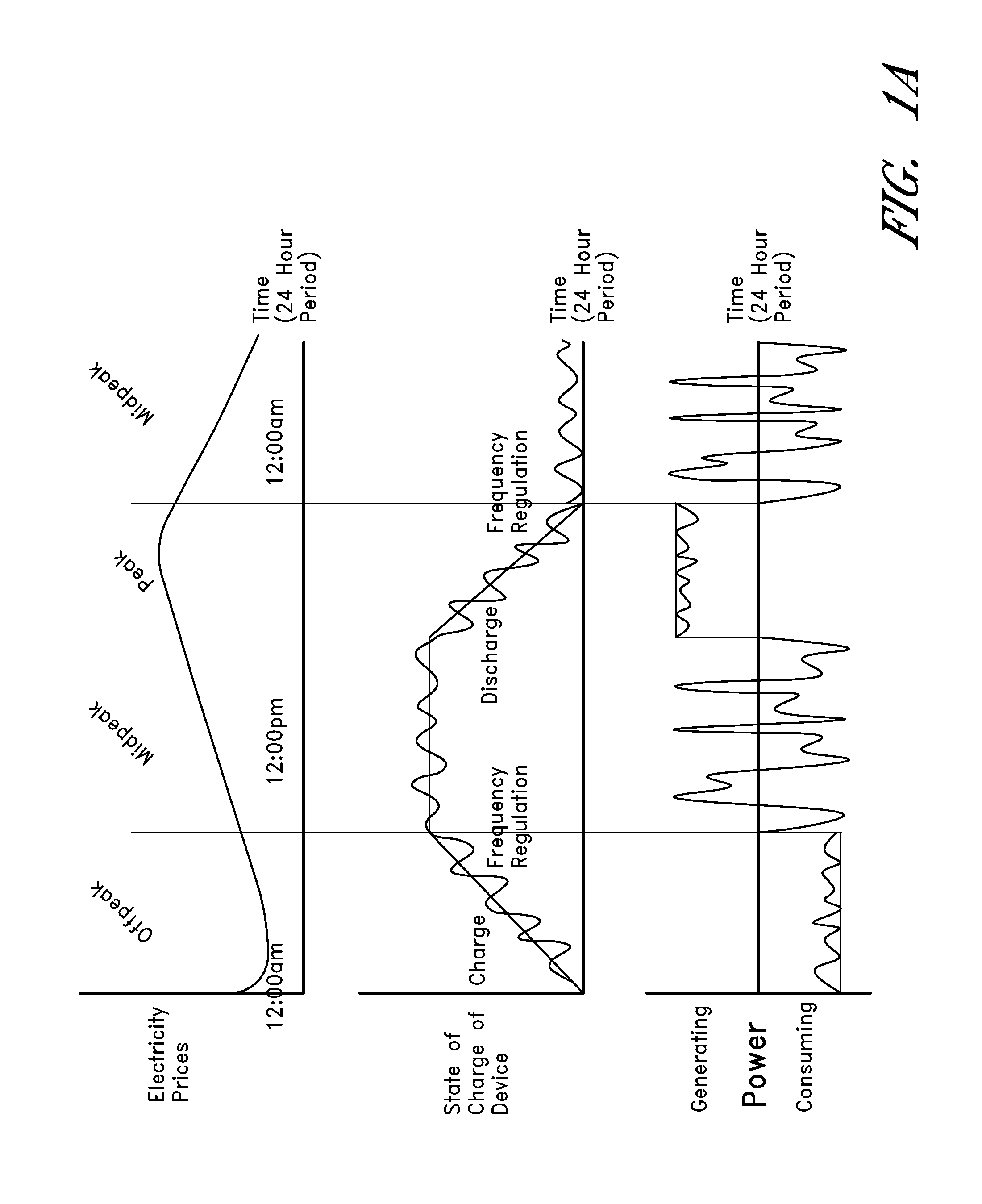
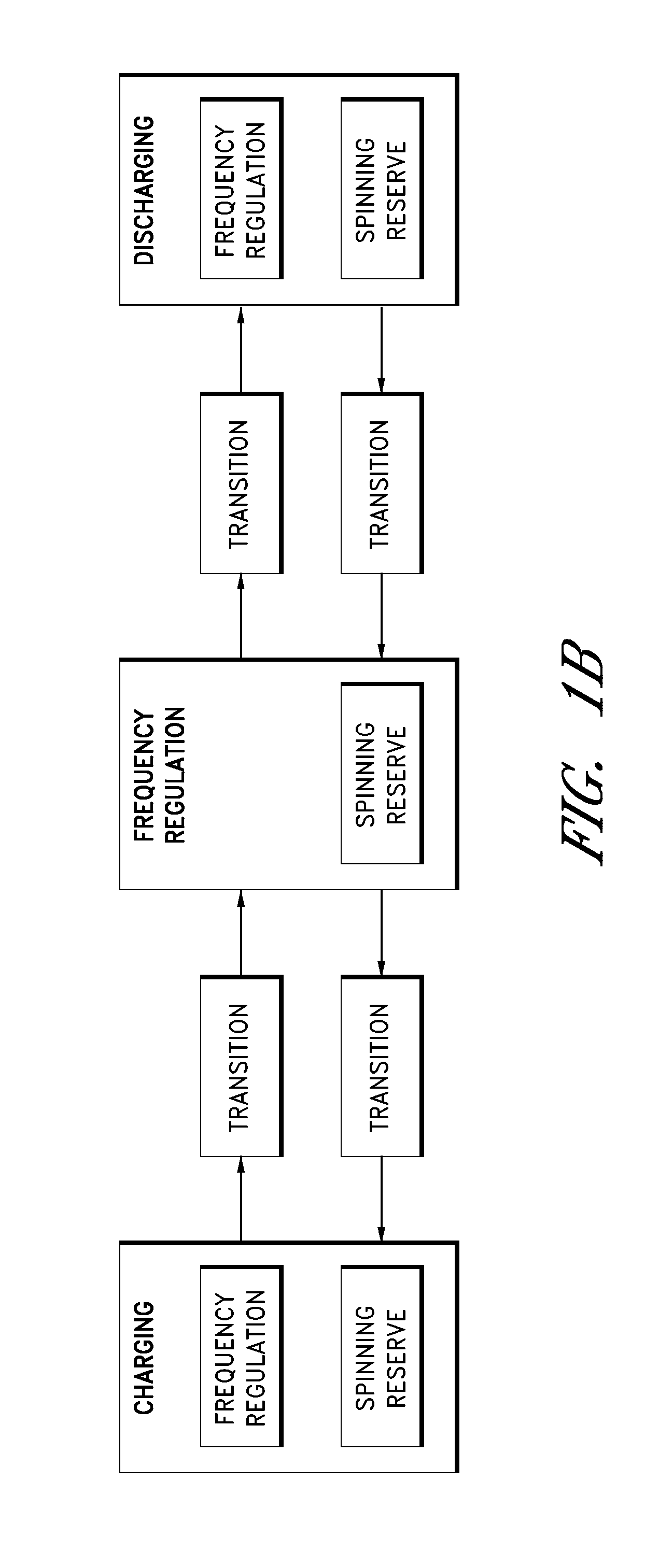
[0007]Some embodiments of the present disclosure relate to novel energy storage systems and methods which can be used to address several energy storage markets and needs, spanning from fast response ancillary services to bulk energy storage. The energy storage devices of the present disclosure can provide support for the stable operation of the electrical grid by storing and then releasing large amounts of energy.
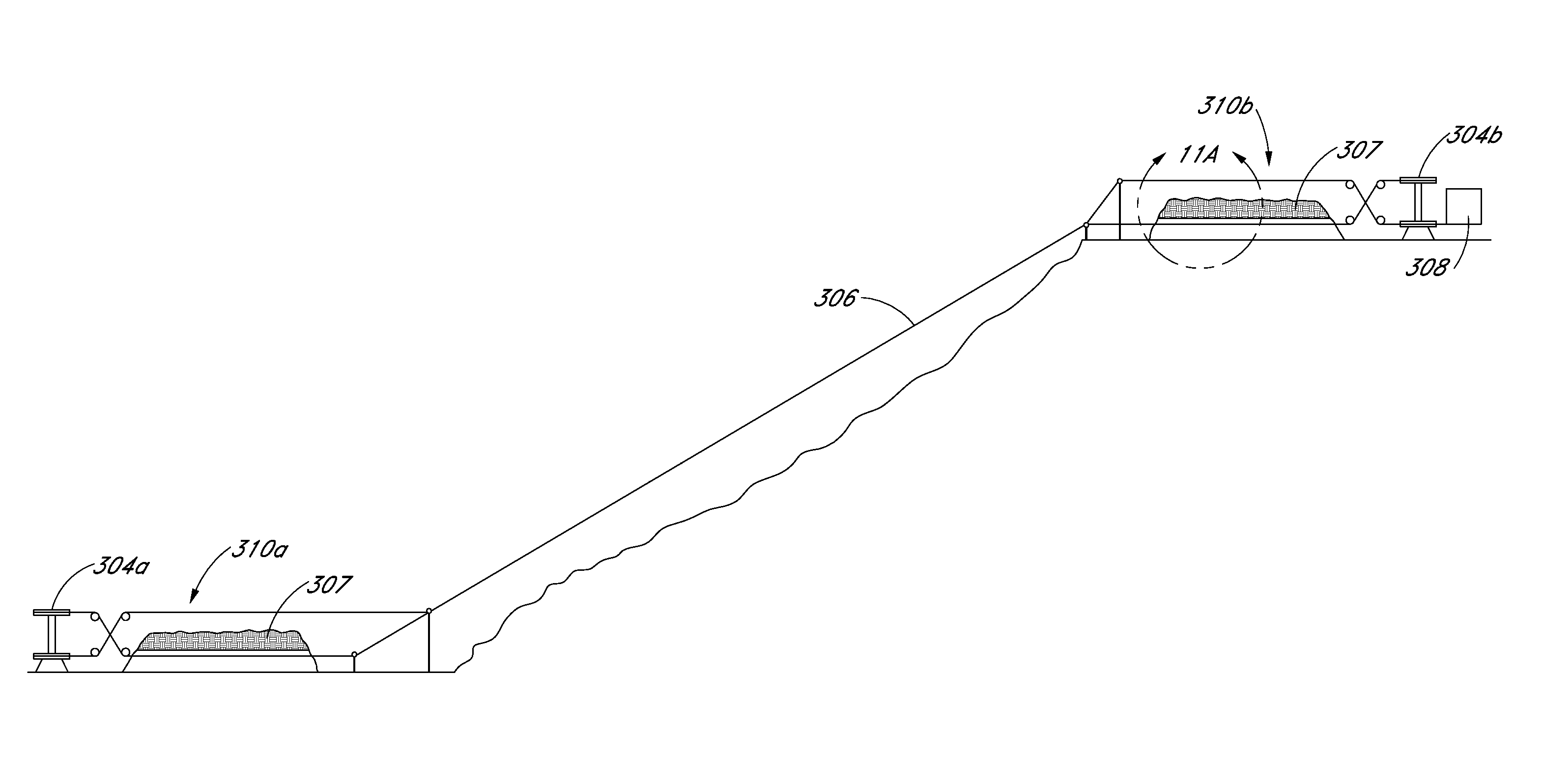
[0008]In some embodiments, the energy storage devices can comprise a plurality of cables or loops of cables that can be positioned adjacent to one another to form an array of cable loops. In some embodiments, the cable loops can be stretched between two bullwheels, from which hooks or carriers can be supported. The hooks or carriers can be used to transport weights from a higher to lower elevation to generate electricity, or from lower to higher elevation to store electrical energy. The overall capacity of the storage installation can be changed by either increasing the wei...
PUM
 Abstract
Description
Claims
Application Information