
Wind turbine with variable speed auxiliary generator and load sharing algorithm

a technology of auxiliary generator and wind turbine, which is applied in the direction of wind turbines, motors, and control multiple engines at the same time, can solve the problems of increasing the cost of power electronics, reducing the efficiency of wind turbines, and creating additional losses

Inactive Publication Date: 2014-03-18
IQWIND
View PDF7 Cites 6 Cited by
  • Summary
  • Abstract
  • Description
  • Claims
  • Application Information

AI Technical Summary

Benefits of technology

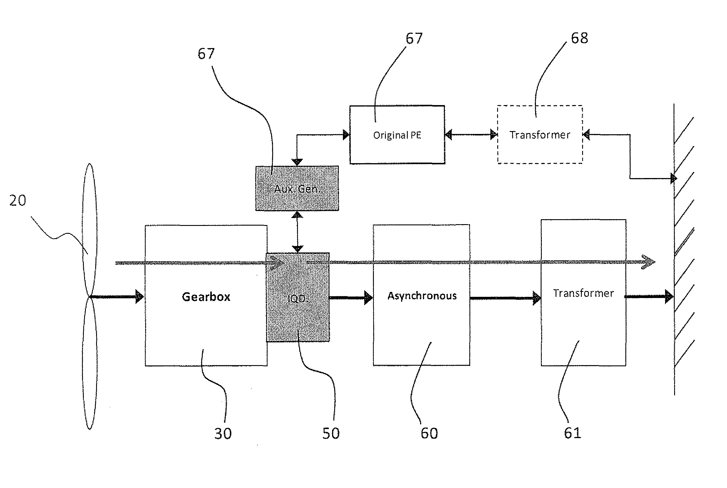
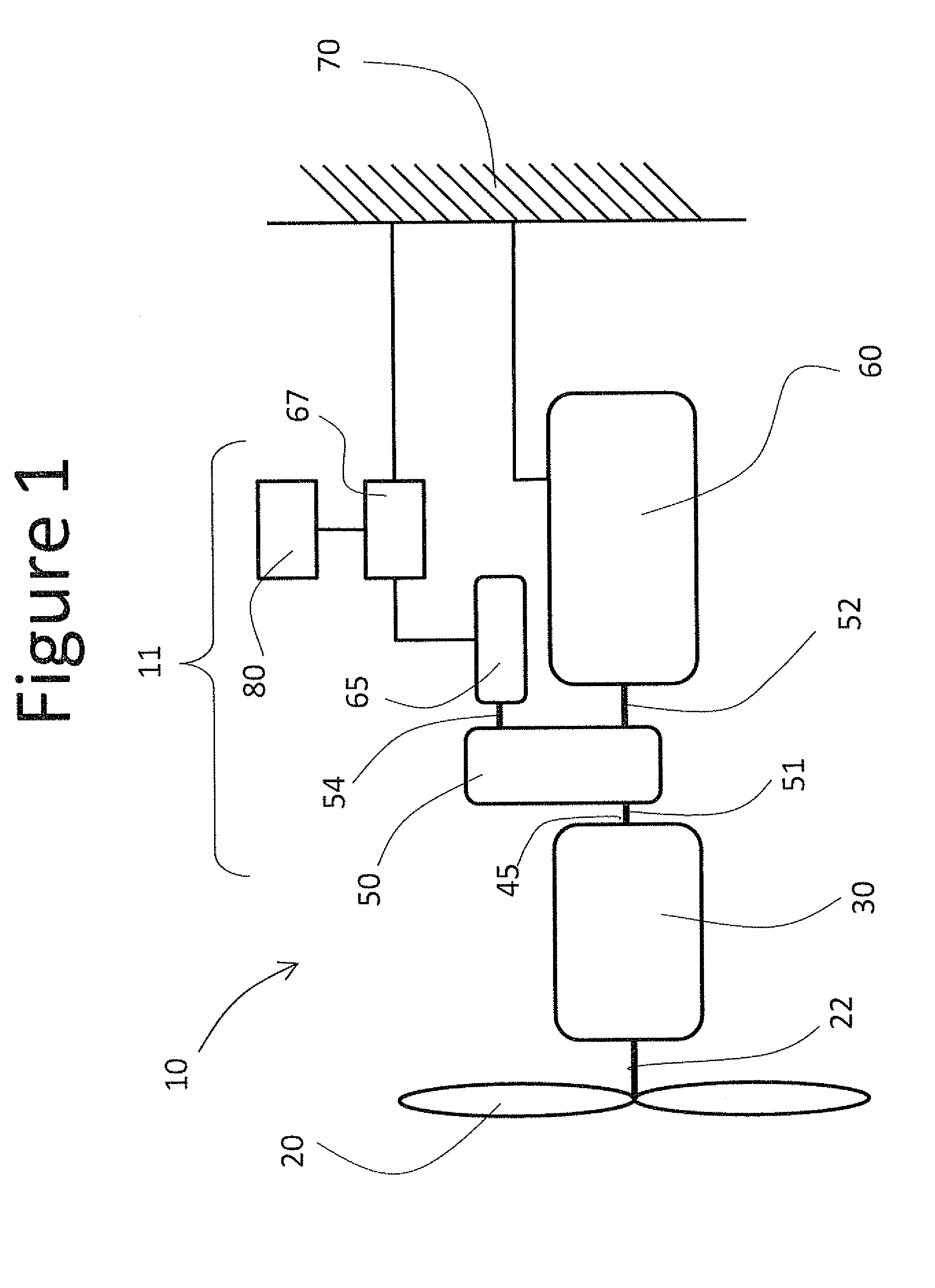
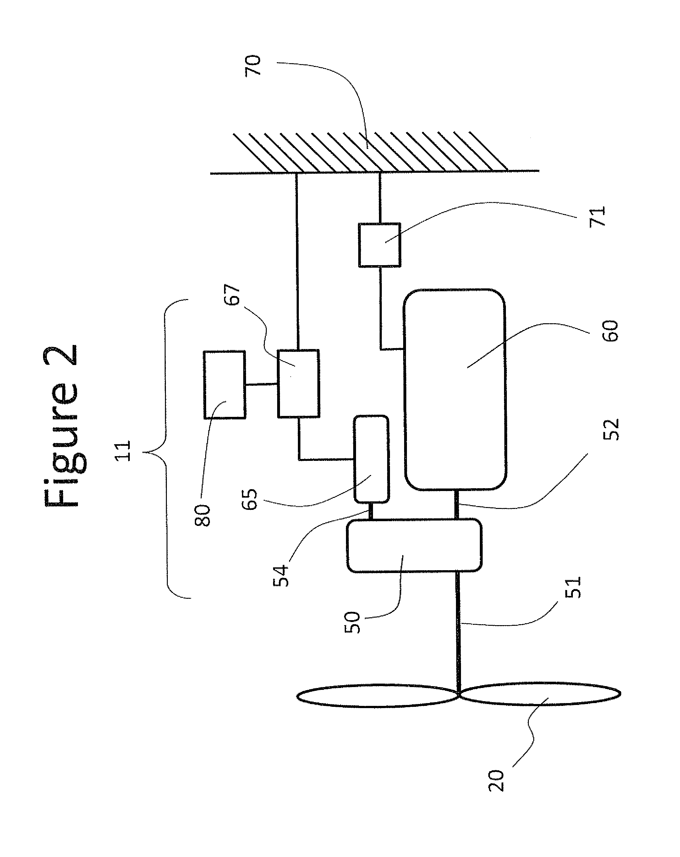
The present invention relates to an assembly for a wind turbine that includes a differential between a main generator and a gear set or a gearless wind turbine, a main generator operating at a constant frequency, a main generator coupled to an electric power grid through power electronics, an auxiliary generator operating at a variable speed, and a controller. The differential has a differential control shaft that changes the ratio between the input and output of the differential. The controller assigns a variable shared load between the auxiliary and main generators based on the efficiency optimization algorithm. The technical effects of the invention include improved efficiency, reduced load on the main generator, and increased flexibility for wind speed and rotor speed.

Problems solved by technology

Their efficiency is never optimized because wind speeds vary and wind input varies.
However, this power electronics is (i) very expensive, (ii) of heavy weight, (iii) unreliable and (iv) creates additional losses.
Another problem is that wind turbines have become an increasing percentage of the turbines that connect to electric power grids and have therefore recently come to be more scrutinized for grid compliance.

Method used


Image

  • Wind turbine with variable speed auxiliary generator and load sharing algorithm
  • Wind turbine with variable speed auxiliary generator and load sharing algorithm
  • Wind turbine with variable speed auxiliary generator and load sharing algorithm

Examples


Embodiment Construction

[0031]The following detailed description is of the best currently contemplated modes of carrying out the invention. The description is not to be taken in a limiting sense, but is made merely for the purpose of illustrating the general principles of the invention, since the scope of the invention is best defined by the appended claims.

[0032]The present invention generally provides a new wind turbine or a retrofitted wind turbine (i.e. fixed speed, doubly fed or fully converted) in which an assembly comprising a differential and an auxiliary generator have been added and in which power electronics between the main generator and the electric grid has been removed (except that in the case of a retrofitted fixed speed turbine, no power electronics was in place so none had to be removed). The removed power electronics may be modified for use as an auxiliary power electronics between the auxiliary generator and the electric grid. The original and the retrofitted wind turbine may be gearles...


PUM

PropertyMeasurementUnit
speedsaaaaaaaaaa
frequencyaaaaaaaaaa
frequenciesaaaaaaaaaa

Abstract

An assembly for retrofitting fixed speed, doubly fed and fully converted wind turbines. A differential having an output shaft coupled to the main generator and a control shaft to change a ratio between differential input and output and coupled to the auxiliary generator. The main generator operates at constant frequency and is coupled to an electric power grid without a power converter. A variable speed auxiliary generator may be coupled to the electric grid through auxiliary power electronics. A controller may during low loads assign a full load to the auxiliary generator, during typical loads assign a variable shared load between the auxiliary and main generators based on an optimization algorithm and during high loads assign a fixed shared load between the auxiliary and main generators based on the internal gear ratio of the differential. For step-down differentials, at high loads the full load may go to the main generator.

Description

FIELD AND BACKGROUND OF THE INVENTION[0001]The present invention relates to apparatuses and methods for wind turbines, and, more particularly to retrofitting wind turbines and new wind turbines having a variable speed auxiliary generator and an algorithm for load sharing with the main generator.[0002]Older wind turbines are of the fixed speed and fixed pitch variety. Their efficiency is never optimized because wind speeds vary and wind input varies. Newer wind turbines (doubly fed turbines and fully converted turbines) are of the variable speed and variable pitch variety. They have a variable output from the gear box which creates a variable frequency and voltage from the generator. Then, in order to be coupled directly to the constant frequency and voltage of the electric grid, these wind turbines employ power electronics, i.e. a converter, (or in the case of a doubly fed turbine a partial converter) to convert the variable frequency and voltage of the generator to the constant fre...

Claims


Application Information

Patent Timeline
Patent Type & Authority Patents(United States)
IPC IPC(8): H02P9/06
CPCF03D7/042Y02E10/723F05B2270/111Y02E10/725F05B2270/103F03D9/002F03D9/25F03D15/10F03D9/255Y02E10/72Y10T29/49002
Inventor EITAN, NIMRODPOZMANTIR, JACKOBZIEGELMAN, GIDEON
Owner IQWIND
Learn More