Plastic suds tub for a washing machine or a washer/dryer

a technology for washing machines and tubs, applied in other washing machines, washing machines with receptacles, textiles and papermaking, etc., can solve the problems of high cost, inability to meet economic mass production, and inability to manufacture tubs with insert-molded support cross technology, etc., to achieve the effect of reducing the use of materials

Inactive Publication Date: 2014-03-25
BSH BOSCH & SIEMENS HAUSGERAETE GMBH
View PDF22 Cites 11 Cited by
  • Summary
  • Abstract
  • Description
  • Claims
  • Application Information

AI Technical Summary

Benefits of technology

[0023]The object of the invention is to embody a tub with stabilization means made exclusively from plastic such that the stability of the tub is high enough for the demands imposed by modern washing machines to be met. It is simultaneously an object of the invention to design the construction of the tub such that the technological outlay involved in manufacturing the tub and the use of materials can be reduced to a minimum.
[0024]The plastic tub designed in accordance with the present invention for a washing machine, especially a washing machine with a front opening for loading and unloading the laundry into or from the machine, which plastic tub features a cylindrical casing and an end face wall closing off the casing with a hollow-cylindrical, solid bearing mount for a bearing of a shaft of a washing drum able to be rotated in the tub as well as means for stabilization, is characterized in that an additional stabilization component is put onto the tub from the outside as a means of stabilizing the end face wall.
[0025]The tub designed in accordance with the invention is characterized by an extraordinary rigidity. The tub is robust enough to withstand a high mechanical stresses which are transmitted from the washing drum onto the tub during the operation of washing machines with a greater drum volume and larger loads. The additional effort involved in implementing the invention is restricted to the use of an additional component made from plastic. With this additional component a lenticular hollow space, possibly subdivided into more or fewer segments separated from each other, is formed on the corresponding end face wall, possible giving a saving in material amounting to 30% to 40% of the material which would have to be expended for cavity-free reinforcement structures, especially ribs or thicker walls. The technologies for producing the additional stabilizing component and for joining the stabilizing component to the end face wall are known and can be managed without any problems.

Problems solved by technology

Translating this type of construction into production is associated with a significant outlay in material and is also very demanding in terms of technology.
Overall such a tub is not suited to economic mass production.
The methods for manufacturing tubs with an insert-molded support cross are technologically demanding and expensive.
In addition the injection molding methods also exhibit a number of problems and disadvantages which stem from the fact that materials are used that have very different properties.
Since the known tubs on the one hand involve a container made of plastic and on the other hand a support cross made from metal, their different material properties have a disadvantageous effect on the cooling-down process after injection molding such that, as a result of the different coefficients of expansion and the different thermal transfer capabilities, numerous stresses are produced after the metallic support cross is molded into the tub which are the result of the plastic shrinking when it cools down to room temperature.
The forces which act on the support cross in such cases are so great that the support cross can distort.
A major disadvantage is that cracks can form in the plastic and the two different materials can came away from each other at the boundaries between them, which can lead after a longer period of operation to failure of the tub seals and to the support cross becoming loose in the end face wall.
A further problem lies in the fact that the plastic inside the material cools down at a different rate from that at the boundary surface of the support cross.
As a result micro gaps form between the plastic and the support cross, which worsens the connection between the materials and can lead to the formation of cracks.
The disadvantage of the construction lies in the stabilizing effect of the additional member being restricted to the area of the bearing mount.
The disadvantage of these tubs is that accumulations of material occur in the areas where the different stress relief profiles cross over each other, which as a result of the different temperature gradients in some areas, causes the material to shrink differently after injection molding.
The result is material stresses within the end face wall with the resulting danger that cracks can form in the material and after a longer period of operation to the seals of the tub failing.
The known constructions of tubs with stabilization means made of plastic described are not able to be used or only able to be used to a restricted extent for larger load volumes and very high spin speeds.
Since more solid plastics essentially make the tub more expensive and strengthening the end face wall and the stress relief profiles leads to accumulations of material, relatively narrow limits are imposed on both options for strengthening the end face wall.
With modern machines in particular, with spin speeds of the rotating drum of over 1500 rpm and a load of more than 8 kg, the known constructions of tub with stabilization means made exclusively of plastic are not able to be used.

Method used


Image

  • Plastic suds tub for a washing machine or a washer/dryer
  • Plastic suds tub for a washing machine or a washer/dryer
  • Plastic suds tub for a washing machine or a washer/dryer

Examples


Embodiment Construction

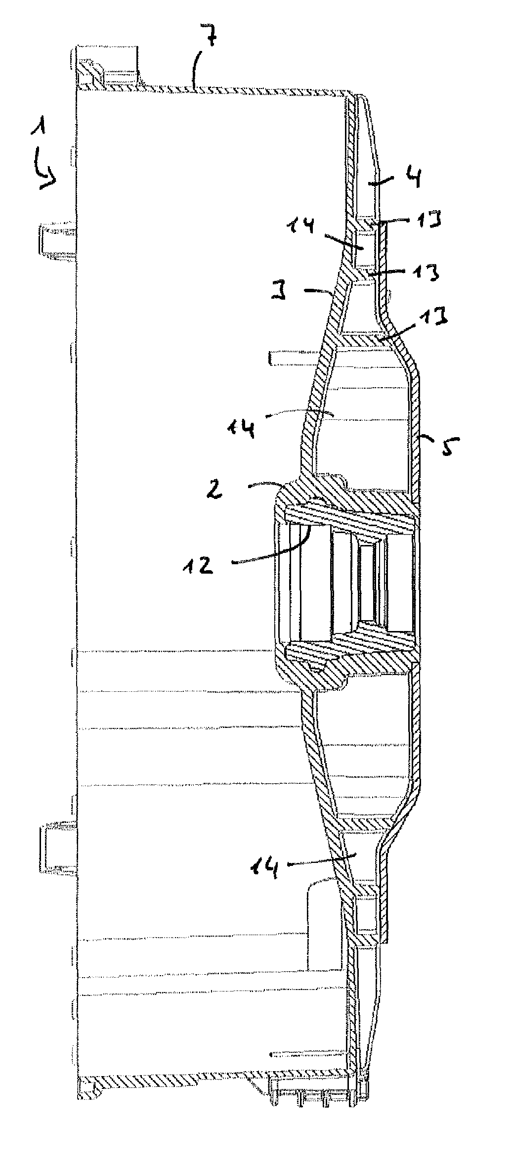
[0042]FIG. 1 shows the rear part of a plastic tub 1 in a perspective view from the front. This component contains the end face wall 3 and is manufactured in one piece by injection molding. In a subsequent operation this component 1 is firmly connected to the cylinder of the tub 1 also made of plastic. Formed a centrally in the end face Wall 3 is a hollow-cylindrical cavity-free bearing mount 2. This is used to receive a fluid-tight bearing not shown in the figure for the drive shaft of a laundry drum also not shown in the figure arranged in the tub 1. The more detailed embodiment of the hollow-cylindrical bearing mount 2 is dictated by the correspondingly exact design of the bearing to be used, which is not of importance here. In any event the bearing mount 2 consists of compact plastic without cavities, since the bearing mount must accept the forces of the rotating washing drum possibly adversely affected by a load imbalance and must be accordingly be designed to accommodate stress...


PUM


Abstract

A plastic suds tub for a washing machine includes a cylindrical casing, an end face wall closing off the casing with a hollow-cylindrical, solid bearing mount, a stabilizer on the end face wall of a more solid and higher-quality plastic than the casing, and reinforcement ribs molded into the stabilizer or end face wall. The reinforcement ribs being radially-aligned from the bearing mount and branching along their radial extent.

Description

BACKGROUND OF THE INVENTION[0001]The invention relates to a plastic suds tub for a washing machine, especially for a washing machine with a front opening for loading and unloading the laundry, which plastic suds tub has a cylindrical casing and an end face wall closing off the casing with a hollow-cylindrical, solid bearing mount for a bearing of a shaft of a laundry drum able to be rotated in the tub as well as means for stabilization.[0002]The invention is based on a washing machine with a housing and a washing assembly suspended on springs within said housing, with the washing mechanism containing a cylindrical plastic suds tub, a washing drum supported to allow it to rotate therein, the axis of which has an essentially horizontal alignment, and a drive motor which drives the laundry drum directly or from outside via an intermediate belt pulley. The end face wall of the suds tub has a bearing mount to support the drum shaft.[0003]Enormous rotational and bending forces arise durin...

Claims


Application Information

Patent Timeline
Patent Type & Authority Patents(United States)
IPC IPC(8): D06F37/26
CPCD06F37/264D06F37/262D06F37/269
Inventor GRACIA BOBED, ISMAELQUANDT, CHRISTIANREICHNER, HOLGERWILDUNG, WILFRIED
Owner BSH BOSCH & SIEMENS HAUSGERAETE GMBH
Why Eureka
Try Eureka