Joining surface treatment device and method

a treatment device and surface treatment technology, applied in the directions of surface pretreatment, transportation and packaging, packaging, etc., can solve the problems of short airing time, undesirable effects, and detrimental to the environment, so as to prevent unnecessary heating of the first component, reduce the energy requirement of the joining surface treatment device and the joining surface treatment method, and achieve no energy waste

Active Publication Date: 2014-03-25
FFT PRODIONSSYST
View PDF13 Cites 68 Cited by
  • Summary
  • Abstract
  • Description
  • Claims
  • Application Information

AI Technical Summary

Benefits of technology

[0032]It is advantageous that the first and second heat sources each have a shape that is adapted to the joining surface and / or they are pivotable about the joining surface.
[0040]With the joining surface treatment device and the joining surface treatment method described above, in a first step, a partial heating of the surface of the first component is performed before applying the primer. Subsequently, in turn after applying the primer to the already previously heated portion of the surface, only a partial heating of the surface of the first component is performed. Herein, in particular warm air or compressed air can be used and preferably infrared radiators can be used. Especially the subsequent heating results in quick airing of the primer. Additionally, by partially heating the surface of the first component only in the portion in which primer has to be applied to the first component, unnecessary heating of the first component is prevented also in other surface portions which are not provided with the primer. Thus, the energy requirement of the joining surface treatment device and of the joining surface treatment method is minimized and no energy is wasted.
[0041]Furthermore, by an optimal adjustment of the primer temperature in the course of and after application to the first component, an optimal or shortest possible airing time of the primer can be provided. Thus, the cycle time for treating a component with the joining surface treatment device and the joining surface treatment method can be optimized and in particular shortened in comparison to the prior art.

Problems solved by technology

In glue joints of components, however, in many cases only portions of the surfaces of the components have to be connected.
In view of the required acceleration of production processes, however, this airing time is not short enough.
Furthermore, it is also disadvantageous that when mixing the soot particles into the primer typically the soot particles are also distributed in the surrounding area.
Furthermore, it is detrimental for the environment that the black primer includes solvents which are released into the environment while airing the black primer.
All these effects are undesirable.

Method used


Image

  • Joining surface treatment device and method
  • Joining surface treatment device and method
  • Joining surface treatment device and method

Examples


second embodiment

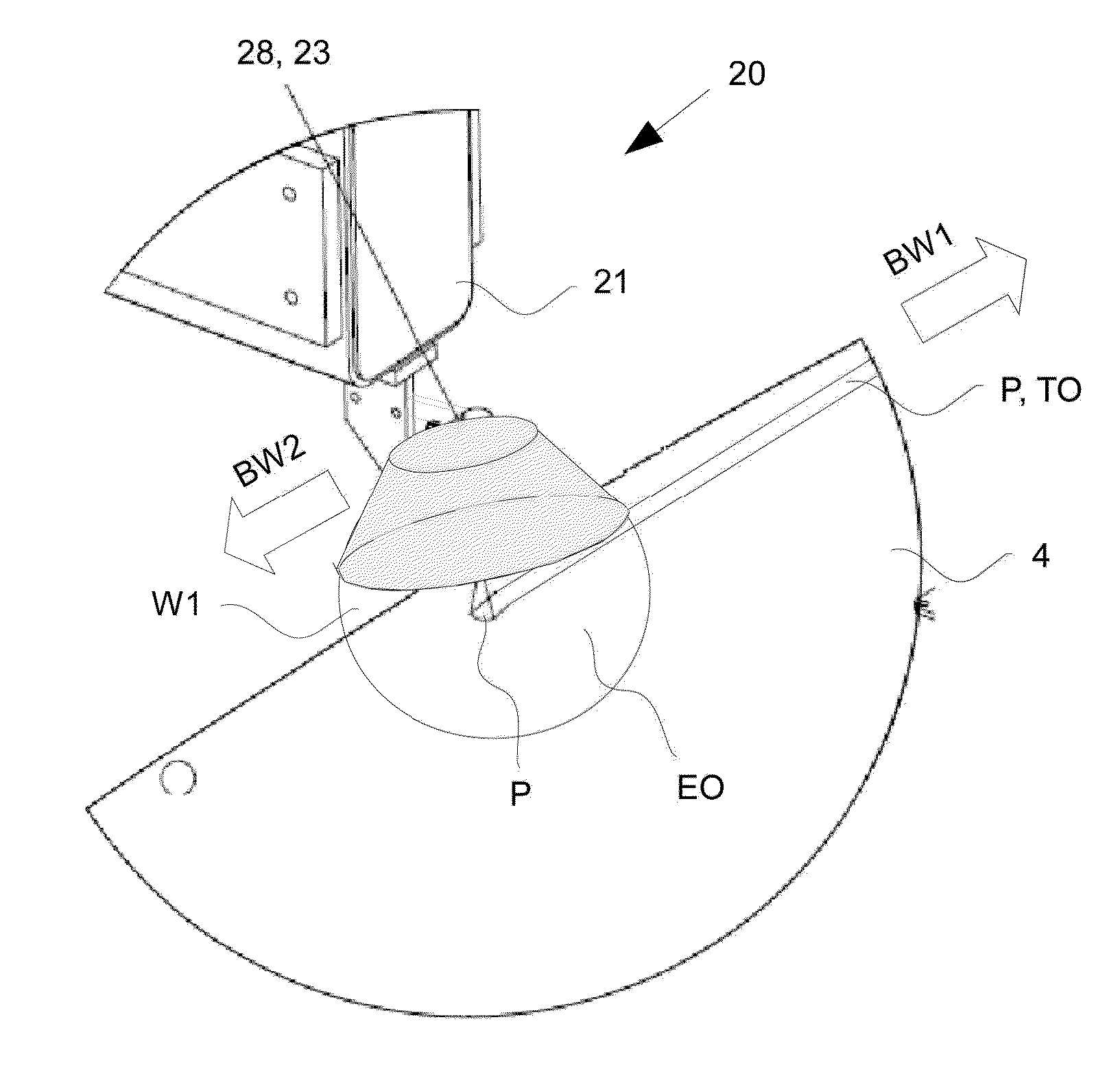
[0071]In the joining surface treatment device 20 instead of two heat sources 22, 24 only one heat source is provided which heats a portion EO of the component 4. The primer application device 23 is arranged approximately in the center of the heat source 28. Thus, the heat source 28 can heat before or after, or preheat and post heat, the portion TO of the surface of the first component 4 at which portion the first component 4 shall be joined with the second component 5 before and also after the application of the primer P to the first component 4.

[0072]The heat source 28 can be, for example, ring shaped with the primer application device 23 arranged in a center of the ring. Thus, in this case the post heating portion is identical to the pre heating portion. The primer application device 23, however, does not have to be arranged in the center of the heat source 28. It is also feasible in particular that the heat source 28 and the primer application device 23 are arranged relative to ...

first embodiment

[0073]Arranging only one heat source 28 relative to the primer application device 23 according to this embodiment is particularly advantageous when the primer has to be applied in a curve to the first component 4, thus, for example, at the corners of the front or rear window of a vehicle 3. Thus, pivoting the heat source 28 can be omitted. On the other hand, the portion EO heated by the heat source 28 is slightly larger than in the

[0074]All other configurations of the second embodiments are identical or analog to those of the first embodiment and are therefore not described in more detail.

[0075]FIG. 8 illustrates a detail of another joining surface treatment device 20 according to a third embodiment analogous to the details of the joining surface treatment device 20 according to the first and second embodiment illustrated in FIGS. 2 and 7. Identical and like elements are provided with identical reference numerals in all embodiments.

[0076]In the joining surface treatment device 20 ac...

third embodiment

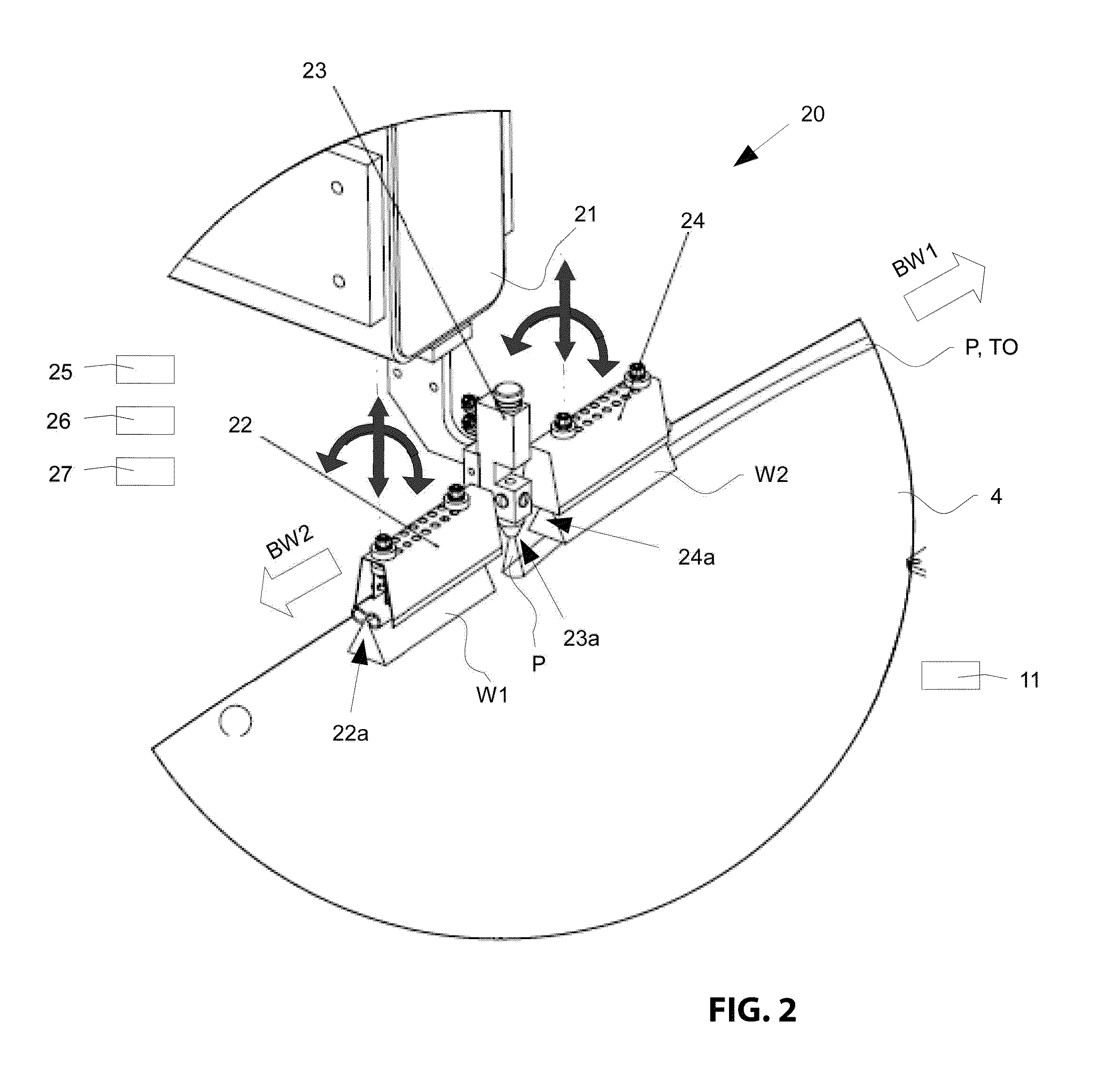
[0086]In case one of the heat sources 22, 24, 28, 29 is configured as an infrared heat source the heat source is advantageously provided with a glare shield or a housing. This can be implemented by the body of the heat source 22, 24, 28, 29 which is illustrated in FIG. 2 through FIG. 4 above the heat source outlet opening 22a, or 24a. As an alternative to a heat source including plural single punctiform radiation emitters 221 through 226 or 241 through 246 as illustrated in FIG. 5 and also in FIG. 2, the first and / or second heat source 22, 24 can also be an X-ray emitter. The same applies for the heat sources 28, 29 of the second and

[0087]For a first heat source 22 an infrared radiation source with 1500 watts power output can be used, wherein an infrared radiation source with 1000 W power is selected as a second heat source 24. Alternatively, an infrared radiation source with 1000 W power can be used as a first heat source 22, wherein an infrared radiation source with 600 W power is...


PUM

PropertyMeasurementUnit
temperatureaaaaaaaaaa

Abstract

A joining surface treatment device and a joining surface treatment method for treating a joining surface of a component which joining surface is used for joining two components, the joining surface treatment device comprising at least one heat source for heating a portion of a surface of a first component at which portion the first component shall be joined with a second component; and a primer application device for applying a primer to a portion of the surface of the first component which portion is heatable by the at least one heat source, wherein the at least one heat source is arranged so that it can heat the first component before and / or after applying the primer.

Description

RELATED APPLICATIONS[0001]This application claims priority from European patent application EP 11 157 081 filed on Mar. 4, 2011 which is incorporated in its entirety by this reference.FIELD OF THE INVENTION[0002]The invention relates to a joining surface treatment device and a joining surface treatment method for treating a joining surface for joining two components. The invention relates in particular to a joining surface treatment device and a joining surface treatment method, wherein a primer or adhesion enhancement agent is applied to a surface of a component in a particular manner before the component is further processed, for example, by a gluing device for gluing it together with another component.BACKGROUND OF THE INVENTION[0003]During industrial fabrication of products made from plural components, components made from different and / or identical materials have to be bonded together by material engagement. For example, the joining technique is used in the motor vehicle indust...

Claims


Application Information

Patent Timeline
Patent Type & Authority Patents(United States)
IPC IPC(8): B29C65/02B32B37/06B29C65/10
CPCC09J5/02B32B38/0036B05B13/0221B05D3/0263B05D3/0227B05B13/0431Y10T156/1798Y10T156/17
Inventor DIETZ, SIEGFRIEDGAMRINGER, FLORIAN
Owner FFT PRODIONSSYST
Why Eureka
Try Eureka