Ventilation fan

a technology of ventilation fan and fan body, which is applied in the field of fans, can solve the problems of inability to operate the ventilation fan, disadvantages of water, dust, or the like entering the housing from the outside, and the need for extra time and cost, and achieves superior waterproof and dustproof mechanisms and simple structures.

Active Publication Date: 2014-03-25
NIDEC CORP
View PDF21 Cites 10 Cited by
  • Summary
  • Abstract
  • Description
  • Claims
  • Application Information

AI Technical Summary

Benefits of technology

[0010]Preferred embodiments of the present invention provide a ventilation fan having a simple structure with superior waterproof and dustproof mechanisms.
[0012]With the above-described configuration, in addition to the provision of the labyrinth structure in the gap between the upper end portion of the outer circumferential wall of the base portion and the lower end portion of the outer circumferential portion of the impeller cup, it is possible to provide a second labyrinth structure in a gap between the upper end portion of the outer circumferential wall of the base portion and the lower end portion of the cylindrical portion. Accordingly, it is possible to realize a ventilation fan having double labyrinth structure with waterproof and dustproof mechanisms with a simple construction.

Problems solved by technology

Depending on the environment in which a ventilation fan is used, water, dust, or the like may disadvantageously enter into the housing from the outside.
If water or dust enters into the motor or the circuit board, this causes a problem in which the motor may break down, so that the ventilation fan cannot operate.
However, the technique requires extra time and cost necessary to form the resin mold, which thus leads to an increase the cost of the ventilation fan.
These requirements cause the structure of the ventilation fan to become complicated.

Method used


Image

  • Ventilation fan
  • Ventilation fan
  • Ventilation fan

Examples


first preferred embodiment

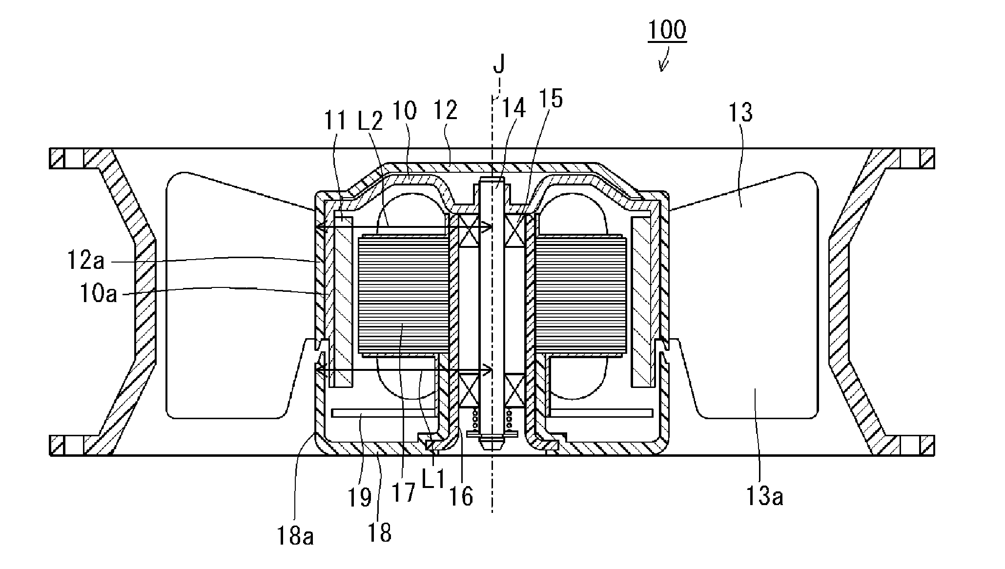
[0029]FIG. 1 is a sectional view schematically showing a construction of a ventilation fan 100 according to a first preferred embodiment of the present invention. An axial fan is exemplarily described in this preferred embodiment, but it is noted that the present invention can also be applied to a centrifugal fan.

[0030]As shown in FIG. 1, a rotor holder 10 having a substantially cylindrical shape is arranged to rotate around a rotation axis J as a center. An impeller cup 12 having a substantially cylindrical shape is fixed to an outer circumference of the rotor holder 10. The impeller cup 12 includes a plurality of blades 13 on an outer circumference thereof. The rotor holder 10 is rotatably supported by a base portion 18 via a shaft 14, a bearing portion 15 including a ball bearing, and a bearing holding portion 16. On an inner circumference of the rotor holder 10, a field magnet 11 is fixed. A stator 17 is fixed to the bearing holding portion 16. The base portion 18 has an outer c...

second preferred embodiment

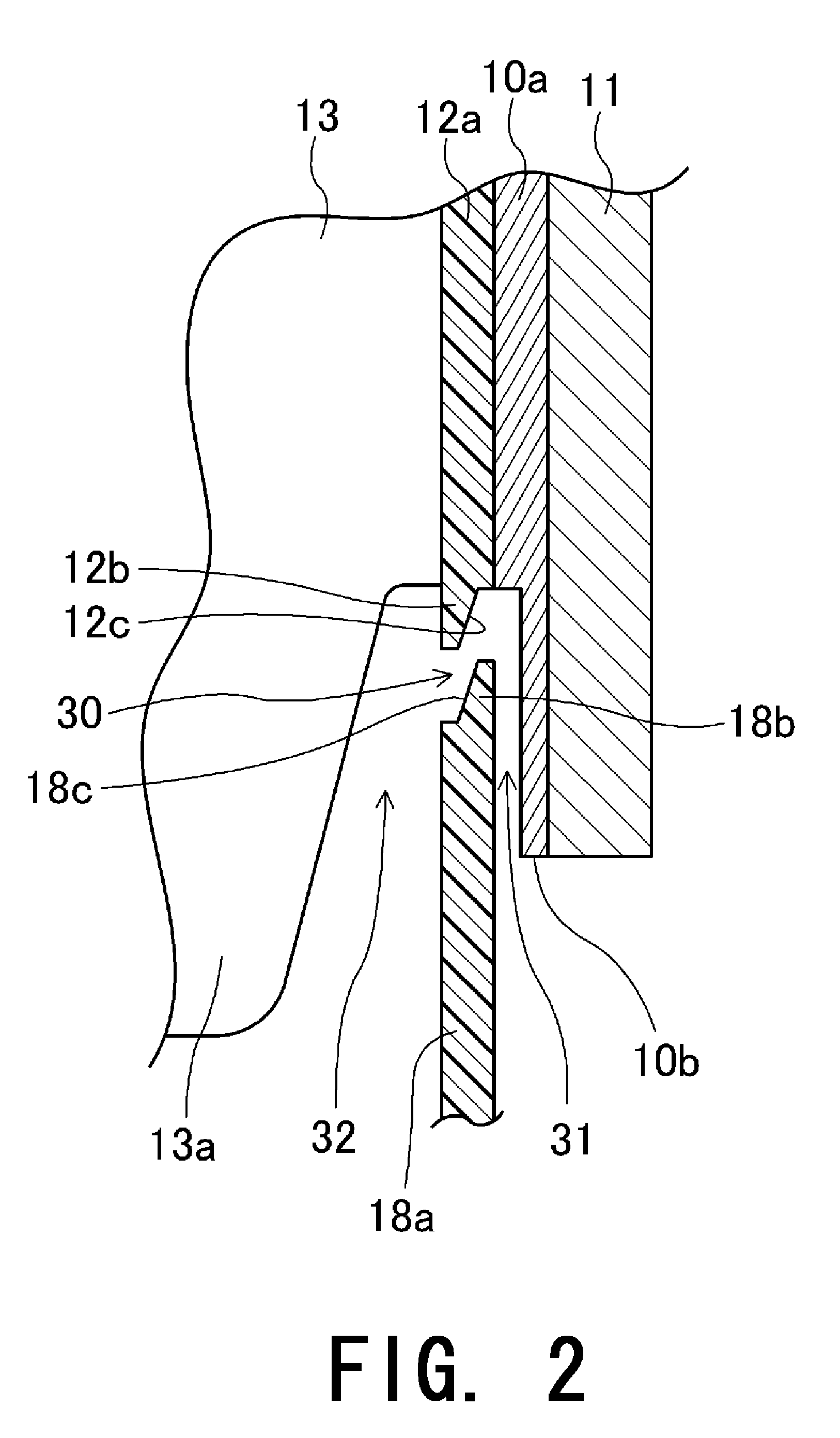
[0040]An impeller cup 12 is fixed on an outer circumference of a rotor holder 10. A plurality of ribs extending in an axial direction are arranged inside an outer circumferential portion 12a of the impeller cup 12. The rotor holder 10 is, for example, press fitted into the impeller cup 12, and fixed thereto.

[0041]In the first preferred embodiment of the present invention, the lower end portion 10b of the outer circumferential portion 10a of the rotor holder 10 is located axially lower than the upper end portion 18b of the outer circumferential wall 18a of the base portion 18, thereby defining the gap 31 which defines the second labyrinth structure. In the second preferred embodiment of the present invention, lower end portions of the plurality of ribs are located axially lower than the upper end portion 18b of the outer circumferential wall 18a of the base portion 18 instead of the outer circumferential portion 10a of the rotor holder 10 to thereby provide a gap 31 which defines the...


PUM


Abstract

A ventilation fan includes a rotor holder rotating around a rotation axis, an impeller cup including a plurality of blades provided on an outer circumference thereof, and a base portion arranged to rotatably support the rotor holder through a bearing portion. The base portion includes an outer circumferential wall extending upwards in an axial direction from an outer circumferential edge portion thereof. A gap defining a labyrinth structure is provided between an upper end portion of the outer circumferential wall of the base portion and a lower end portion of an outer circumferential portion of the impeller cup. A lower end portion of a cylindrical portion is located axially lower than the upper end portion of the outer circumferential wall of the base portion.

Description

BACKGROUND OF THE INVENTION[0001]1. Field of the Invention[0002]The present invention relates to a fan. More specifically, the present invention relates to a ventilation fan including waterproof and dustproof mechanisms.[0003]2. Description of the Related Art[0004]A ventilation fan such as an axial fan or a centrifugal fan typically includes an impeller having a plurality of blades, a motor arranged to rotate the impeller, and a circuit board for motor rotation control. Each of the impeller, the motor, and the circuit board are accommodated in a housing.[0005]Depending on the environment in which a ventilation fan is used, water, dust, or the like may disadvantageously enter into the housing from the outside. If water or dust enters into the motor or the circuit board, this causes a problem in which the motor may break down, so that the ventilation fan cannot operate.[0006]In view of such a problem, Japanese Laid-Open Patent Publication No. 10-191611 discloses a technique in which a...

Claims


Application Information

Patent Timeline
Patent Type & Authority Patents(United States)
IPC IPC(8): F01D11/02F01D11/00F04D29/08F04B35/04F04B17/00
CPCF04D25/0613F04D29/083
Inventor NOGAMI, SAKAEYOKOTANI, HIROTSUGUIWAMOTO, KENJI
Owner NIDEC CORP
Why Eureka
Try Eureka