Dust collector

a dust collector and dust collector technology, applied in the direction of dispersed particle separation, separation processes, chemistry apparatuses and processes, etc., can solve the problems of reducing the service life of the dust collector, generating a large amount of waste gas, and corroding dust, etc., to reduce the backpressure, increase the area, and facilitate the flow of air into the air flow channel

Active Publication Date: 2014-03-25
MICRON TECH INC
View PDF2 Cites 4 Cited by
  • Summary
  • Abstract
  • Description
  • Claims
  • Application Information

AI Technical Summary

Benefits of technology

[0008]The primary objective of the present invention is to provide a dust collector, which does not collect dust in a single area but can uniformly catch dust, whereby is prolonged the service life of the dust collector.
[0011]The overlapped pores in the superimposition region can reduce backpressure and make the air flow easily pour into the air flow channel. The baffle boards can increase the area that the air flow contacts the catch boards and the time that the air flow stays in the air flow channel, whereby the catch boards can catch dust more efficiently and uniformly, and whereby dust is deposited on the catch boards uniformly. Therefore, the present invention can prolong the service life of the dust collector, decrease the frequency of replacement and reduce the cost of cleaning and maintenance.

Problems solved by technology

A considerable amount of waste gas is generated by the CVD process and needs processing by a detoxifier before exhaust.
After cooling down, the waste gas will condense into corrosive dust.
Thus is obviously decreased the service life of the dust collector 1.
Thus is prolonged the maintenance downtime, decreased the productivity, and increased the fabrication cost.

Method used


Image

  • Dust collector
  • Dust collector
  • Dust collector

Examples


Embodiment Construction

[0024]The embodiments are used to demonstrate the present invention below.

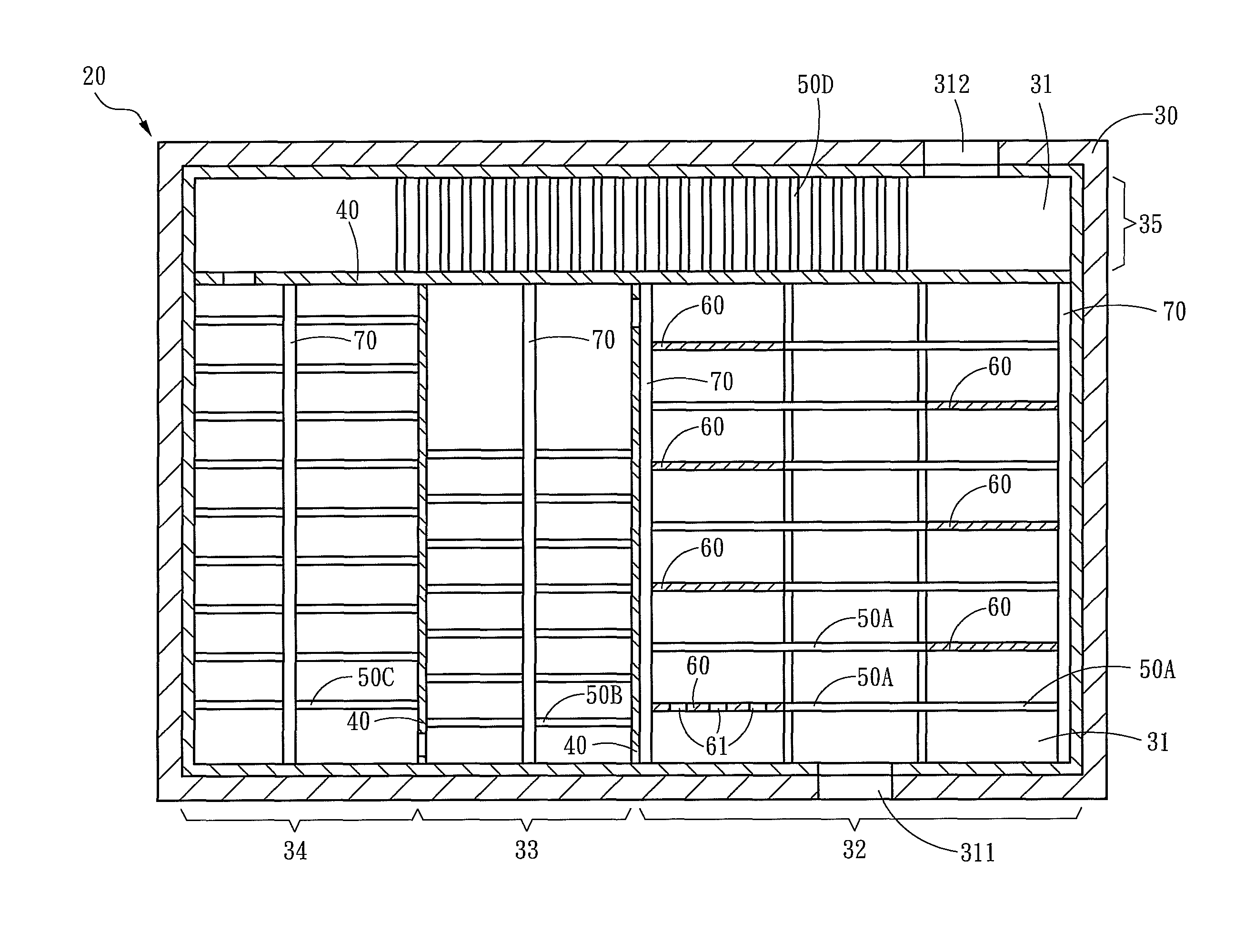
[0025]Refer to FIGS. 4-9. The dust collector 20 of the present invention is used to catch dust in an air flow 10 (as shown in FIG. 10) and comprises a box 30, a plurality of separating boards 40, a plurality of catch boards 50A, 50B, 50C, and 50D, and a plurality of baffle boards 60. The separating boards 40 partitions the box 30 to form an air flow channel 31. The air flow channel 31 has an inlet 311 and an outlet 312. The air flow channel 31 is divided into an incoming region 32, a first catch region 33, a second catch region 34, and an outgoing region 35.

[0026]The catch boards 50A, 50B, 50C and 50D are arranged in the air flow channel 31 and respectively have a plurality of pores 51A, 51B, 51C and 51D. The catch board boards 50B, 50C and 50D are respectively arranged in the first catch region 33, the second catch region 34 and the outgoing region 35. The pores 51B, 51C or 51D of each of the catch board boar...


PUM

PropertyMeasurementUnit
areaaaaaaaaaaa
diameteraaaaaaaaaa
plurality of poresaaaaaaaaaa

Abstract

A dust collector for catching dust generated by temperature drop comprises a box, a plurality of separating boards, a plurality of catch boards, and a plurality of baffle boards. The separating boards partition the box to form an air flow channel. The catch boards and the baffle boards are staggered in the air flow channel; a portion of the catch boards are arranged in a central column to form a superimposition region along the vertical direction. The pores of the catch boards in the superimposition region are overlapped to make the air flow pour into the air flow channel easily. The baffle boards are staggered at the left or right of the catch boards, whereby the air flow takes more time to have a longer travel in the air flow channel, and dust is not accumulated in a single area but uniformly caught by the catch boards.

Description

FIELD OF THE INVENTION[0001]The present invention relates to a waste gas processing device for the CVD process, particularly to a dust collector collecting dust in waste gas.BACKGROUND OF THE INVENTION[0002]The chemical vapor deposition (CVD)method is a film forming process frequently used in the semiconductor industry, wherein a liquid material is heated into a vapor reacting with special gases, and wherein the product then contacts and deposits on specified areas to form a film.[0003]A considerable amount of waste gas is generated by the CVD process and needs processing by a detoxifier before exhaust. After cooling down, the waste gas will condense into corrosive dust. In order to avoid dust pollution and reduce the burden of the detoxifier, the dust is filtered beforehand.[0004]Refer to FIG. 1 for a conventional dust collector. In order to filter out dust, let waste gas pass through a conventional dust collector 1. The conventional dust collector 1 has an inlet 2 and an outlet 3....

Claims


Application Information

Patent Timeline
Patent Type & Authority Patents(United States)
IPC IPC(8): B01D45/00
CPCB01D45/08
Inventor LU, CHIN HSIUWANG, CHIN MING
Owner MICRON TECH INC
Why Eureka
Try Eureka