
Tunable two-mirror interference lithography system

a lithography system and mirror interference technology, applied in the field of optical lithography systems, can solve the problems of laborious realignment of the entire optical path, difficult to tune the pattern periodicity, and high-power lasers that are costly, and achieve the effect of convenient regulation and uniform pattern periodicities

Inactive Publication Date: 2014-03-25
STEVENS INSTITUTE OF TECHNOLOGY
View PDF2 Cites 7 Cited by
  • Summary
  • Abstract
  • Description
  • Claims
  • Application Information

AI Technical Summary

Benefits of technology

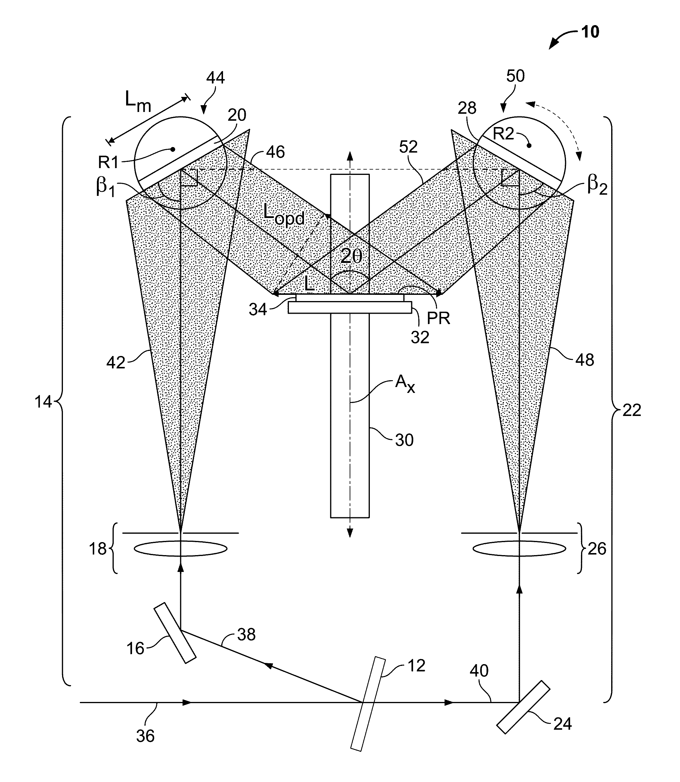
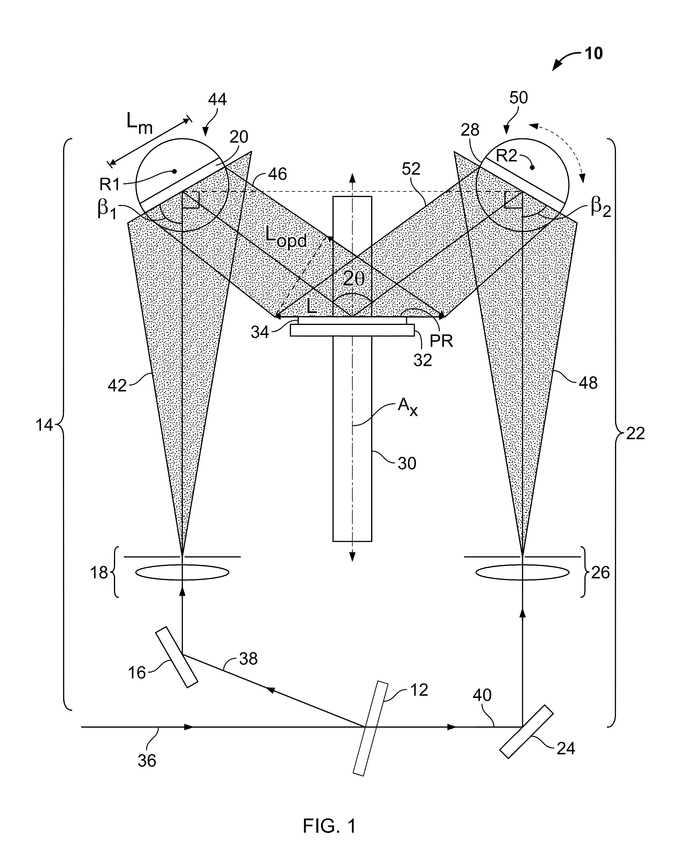
The present invention offers a two-beam interference lithography system that can create large-area nanopatterns with the ability to adjust pattern periodicities. This is achieved by using rotatable mirrors in the beam paths, which can be adjusted for different pattern periodicities. The minimum pattern coverage area of the invention is determined by the optical coherence length and mirror size, and only three components need to be adjusted to select the pattern periodicity and area covered. Overall, this invention provides greater flexibility and precision in nanopatterning.

Problems solved by technology

However, the fixed optical path of the conventional two-beam IL system makes it difficult to tune the pattern periodicity, in that it requires the laborious realignment of the entire optical path to vary the pattern period.
Additionally, it is necessary to provide a large optical table and a costly high-power laser to provide enough exposure power over the long distance travelled by the expanded beams.

Method used


Image

  • Tunable two-mirror interference lithography system
  • Tunable two-mirror interference lithography system
  • Tunable two-mirror interference lithography system

Examples


example

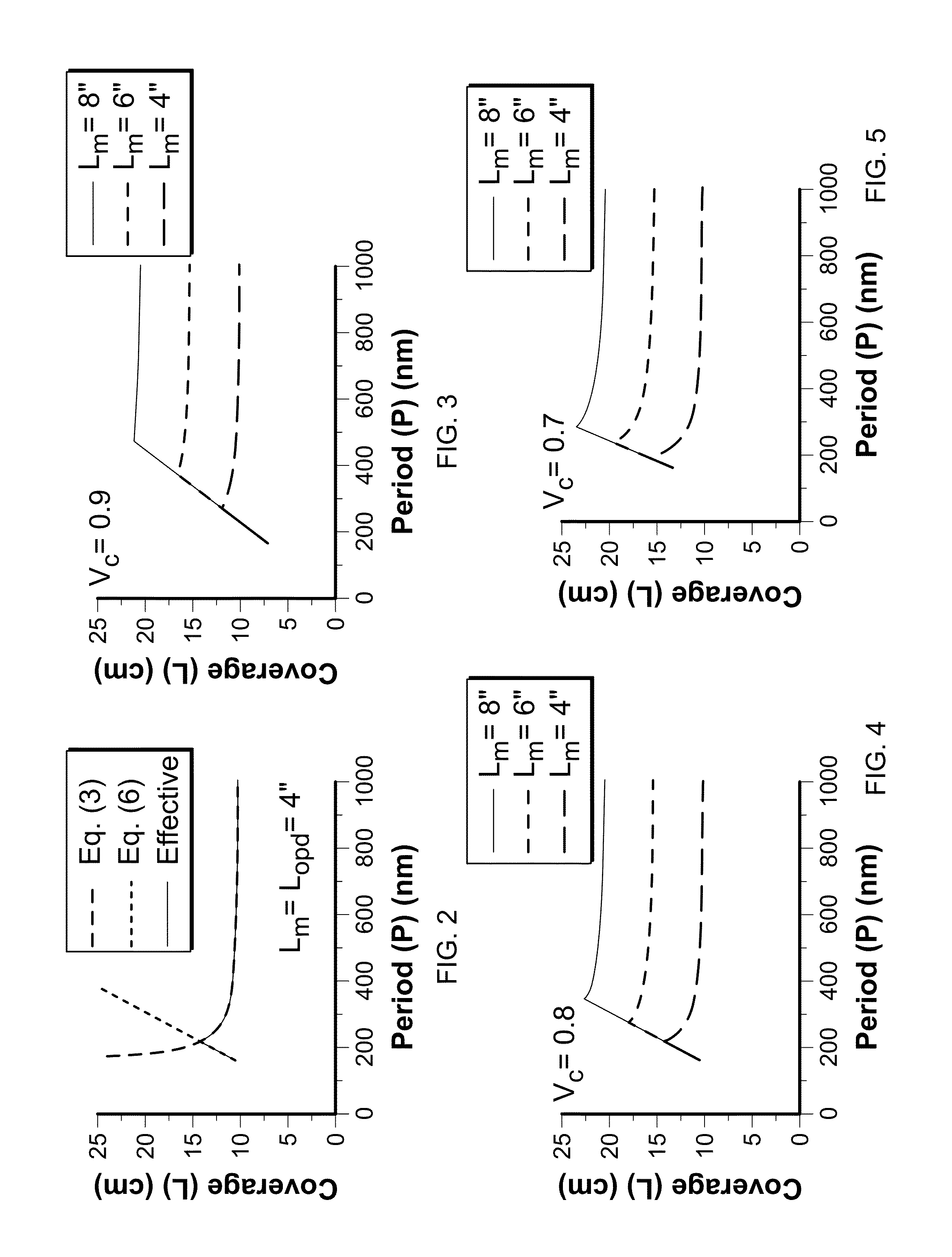
[0033]To experimentally demonstrate the performance of the exemplary interference lithography system 10 of FIG. 1, and predicted performance of such as system 10 as discussed with respect to FIGS. 2-5, 1-D interference nano-grating patterns of various periodicities were fabricated on 4-inch silicon substrates using a 50 mW HeCd laser (Kimmon Electric US, LP, Centennial Colo.) of λ=325 nm and σ=425 Mhz (coherence length of ˜30 cm) and two 4-inch rotating mirrors. FIGS. 6 and 7 are photographs of the experimental interference lithography system that was used. This experimental system is a significantly simplified embodiment of the interference lithography system of the present invention, but included a sufficient number of components to demonstrate the performance of other embodiments of the invention. The components of FIGS. 6 and 7 are referenced by the same reference numbers used to indicate the schematic representation of those components in FIG. 1, with additional reference numbe...


PUM


Abstract

A two-beam interference lithography system offers large-area nanopatterning with tunability of pattern periodicities. The tunable feature is achieved by placing two rotatable mirrors in the two expanded beam paths which can conveniently be regulated for the designed pattern periodicities. While the effective interference pattern coverage is mainly determined by the optical coherence length and mirror size, the minimum pattern coverage area is as large as the effective coherence length of the laser and the selected mirror size over a wide range of periodicities.

Description

CROSS-REFERENCE TO RELATED APPLICATIONS[0001]The present application claims the benefit of U.S. Provisional Patent Application No. 61 / 507,375, filed on Jul. 13, 2011, the disclosure of which is incorporated by reference herein in its entirety.STATEMENT REGARDING FEDERALLY SPONSORED RESEARCH[0002]Not applicable.FIELD OF THE INVENTION[0003]The present invention relates to an optical lithography system, and more particularly, to a tunable two-mirror interference lithography system.BACKGROUND OF THE INVENTION[0004]Laser interference lithography has been widely used as an effective and inexpensive technique for the fabrication of uniform nanopatterns and photonic materials on substrates. There are various geometrical configurations of interference lithography (IL) systems, the two major system configurations being the Lloyd's mirror interferometer and the conventional two-beam interferometer, such as a Mach-Zehnder interferometer. A Lloyd's mirror interferometer includes a mirror oriente...

Claims


Application Information

Patent Timeline
Patent Type & Authority Patents(United States)
IPC IPC(8): G02B7/198
CPCG02B26/0816G03F7/70408
Inventor MAO, WEIDONGWATHUTHANTHRI, ISHANCHOI, CHANG-HWAN
Owner STEVENS INSTITUTE OF TECHNOLOGY
Learn More