Stress reduction means for warp control of substrates through clamping

a clamping and stress reduction technology, applied in the direction of soldering equipment, manufacturing tools, auxillary welding devices, etc., can solve the problems of large sample to sample variation (sigma) of warp, thermal warp, and potential non-wet or unequal c4 solder height, so as to minimize the variation in the height of the solder ball

Active Publication Date: 2014-04-01
GLOBALFOUNDRIES U S INC
View PDF5 Cites 7 Cited by
  • Summary
  • Abstract
  • Description
  • Claims
  • Application Information

AI Technical Summary

Benefits of technology

[0007]A method is provided for bonding a semiconductor chip to a packaging substrate while minimizing the variation in the solder ball heights and controlling the stress in the solder balls and the stress in the packaging substrate. During the solder reflow, the warp of the packaging substrate, including the absolute warp, thermal warp, and substrate to substrate variations of the warp, is constrained at a minimal level by providing a clamping constraint to the packaging substrate. During cool down of the solder balls, the stresses and strains of the solder joints are maintained at levels that do not cause tear of the solder joints or breakage of the packaging substrate by removing the clamping constraint. Thus, the bonding process provides both uniform solder height with minimized solder non-wets and stress minimization of the solder balls and the packaging substrate.

Problems solved by technology

Substrate warp poses a challenge for the attachment of a semiconductor chip to a packaging substrate using flip-chip technology.
A large warp in magnitude at reflow is a cause for unreliable C4 bonding, leading to potential non-wets or unequal C4 solder heights.
In addition, a large sample to sample variation (sigma) of warp is a problem during bond and assembly even for substrates having a nominal mean warp.
The thermal warp, i.e., the change in warp with temperature, is another undesirable problem for bond and assembly.
Such change in the shape of the substrate could lead to defects in the solder ball joints such as hot tears.
This results in the build-up of shear stresses in the C4 balls and the semiconductor chip.
If the free bending of the bonded assembly including the semiconductor chip and the packaging substrate is restricted by use of the TGC, the reduction of stresses and strains cannot be achieved.
Limiting the free bending of the bonded assembly can thus lead to an effective increase in failures in the C4 balls and BEOL metallurgy.
Measurements on actual TGC mounted substrates have shown that such a large reduction in CTE is very difficult to achieve, and is highly dependent on the adhesive being used.
Soft adhesives allow slippage between the substrate and the glass, and do not achieve a sufficient reduction in CTE.
Harder adhesives can reduce the CTE more, but result in either permanently deforming the substrate or breaking the glass.
The TGC also has the drawback of requiring an adhesive to attach the packaging substrate to the glass.
Due to this phenomenon, the TGC technique cannot be used with LGA substrates where contamination is not tolerable.
The removal of the packaging substrate from the TGC is also an issue.
The technique of shearing a bonded package off the TGC is stressful to the packaging substrate.
Through substrate vias in the packaging substrate are particularly vulnerable to damage during this process.

Method used


Image

  • Stress reduction means for warp control of substrates through clamping
  • Stress reduction means for warp control of substrates through clamping
  • Stress reduction means for warp control of substrates through clamping

Examples


first embodiment

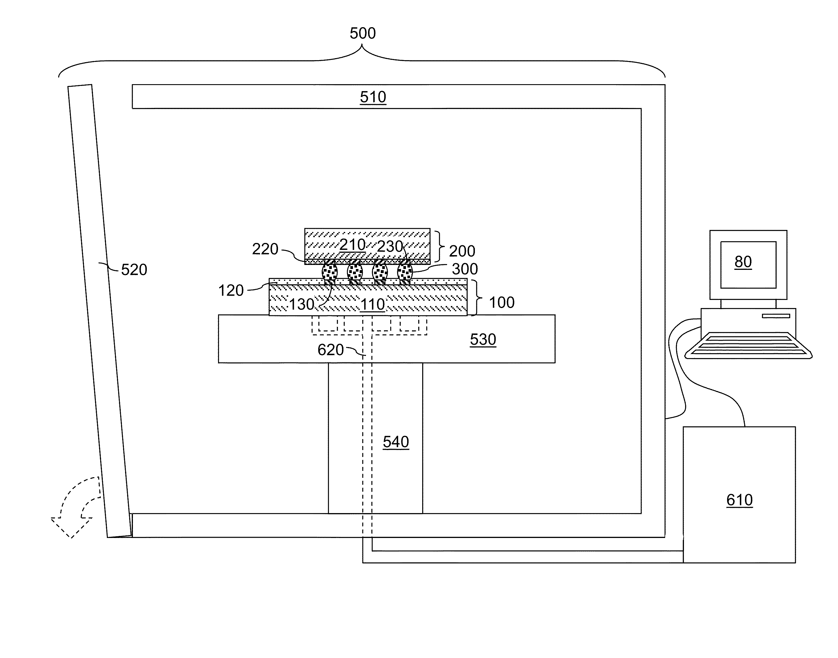
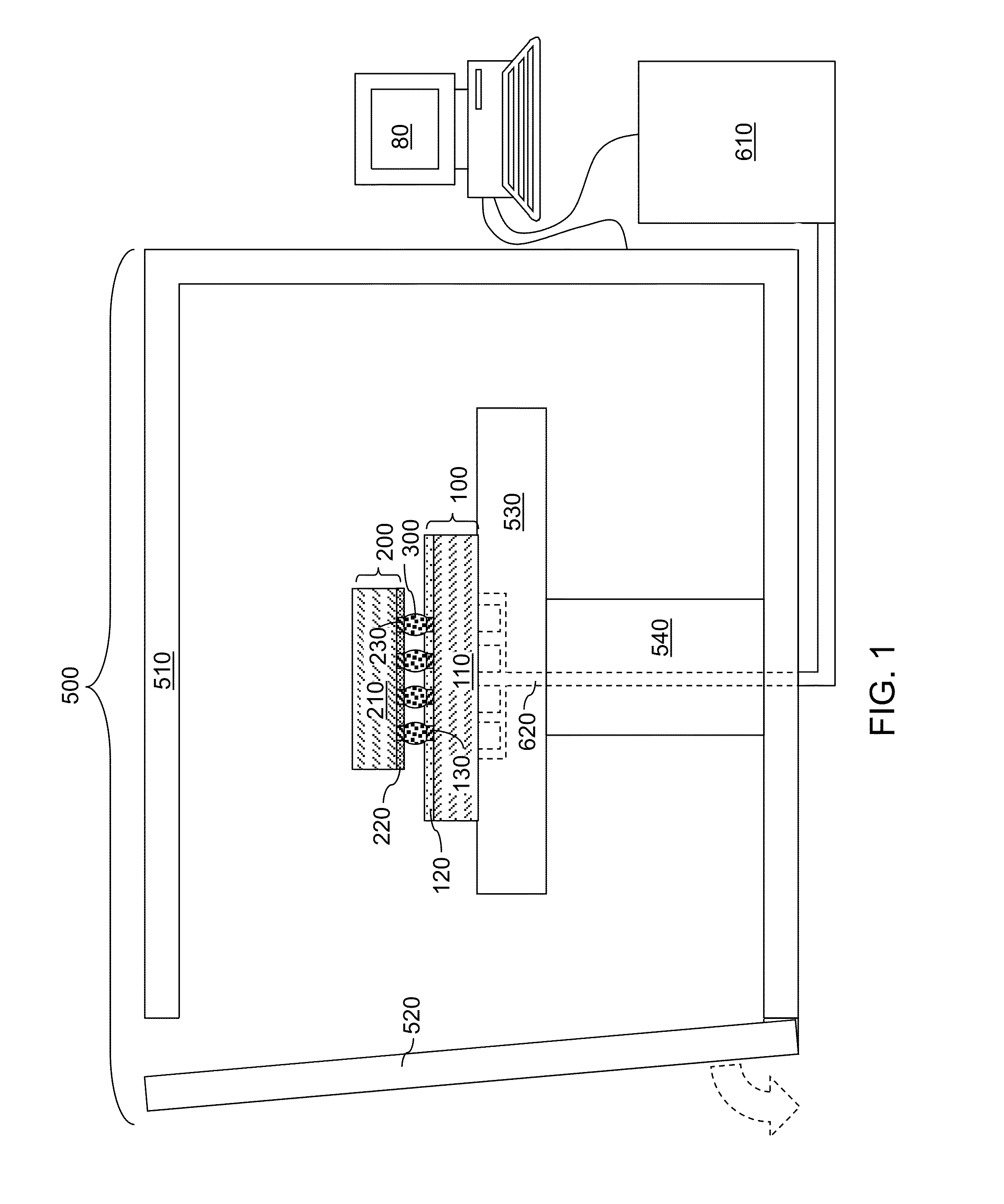
[0025]Referring to FIG. 1, a first exemplary apparatus according to the present disclosure is illustrated, which can be employed for bonding a first substrate 100 to a second substrate 200.

[0026]The first substrate 100 can include a first substrate layer 110, a first surface dielectric layer 120, and an array of first bonding pads 130 embedded within the first surface dielectric layer 120. The first substrate 100 can be a packaging substrate or a semiconductor chip or an interposer. If the first substrate 100 is a packaging substrate, the first substrate 100 can include layers of wiring structures (metal interconnect structures), and can be a ceramic substrate, an organic laminated substrate, a silicone substrate, a metal substrate, or a flexible film substrate. If the first substrate 100 is a semiconductor chip, the first substrate 100 includes semiconductor devices therein.

[0027]The second substrate 200 includes a second substrate layer 210, a second surface dielectric layer 220, ...

second embodiment

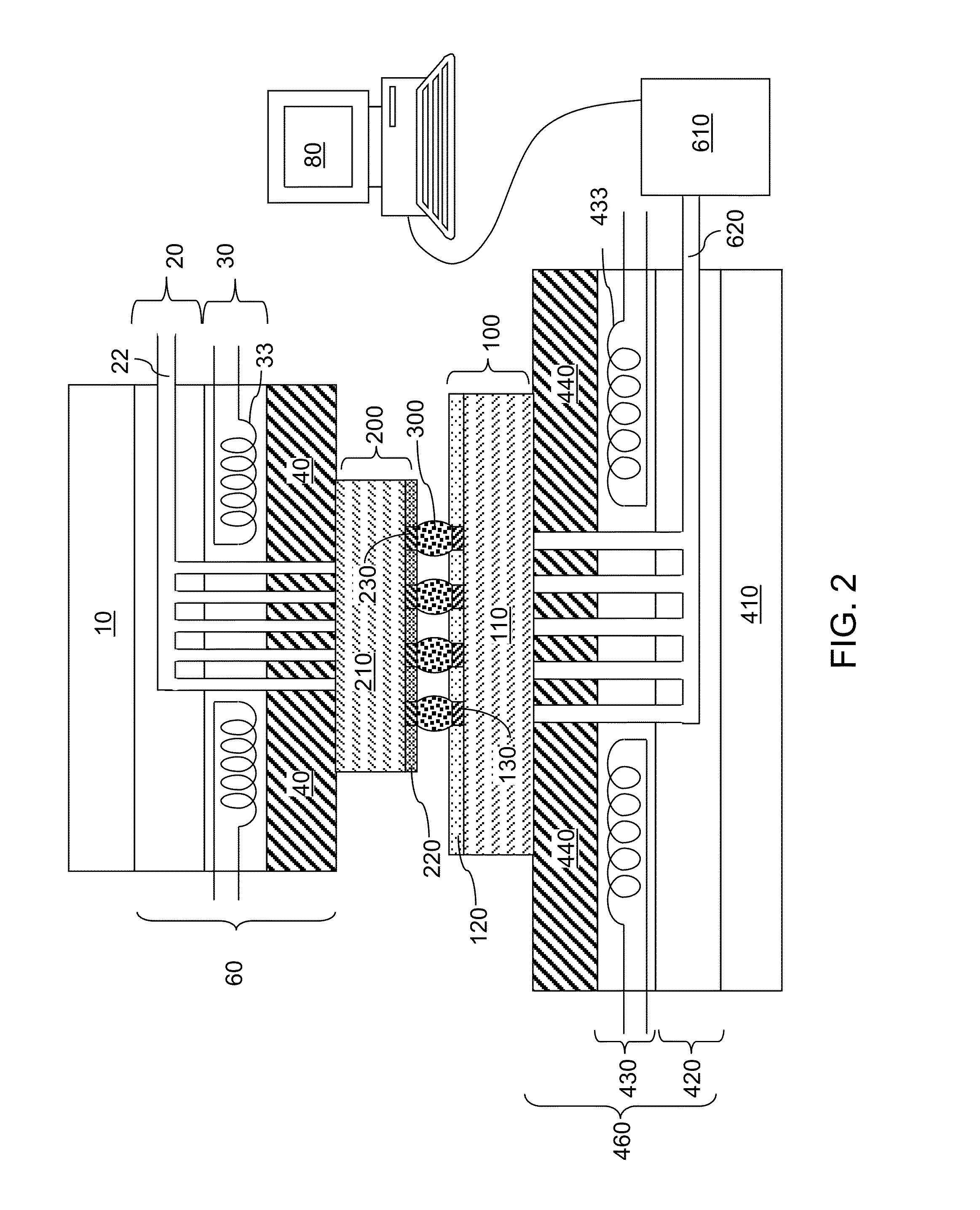
[0040]Referring to FIG. 2, a second exemplary apparatus according to the present disclosure includes a chip bonder configured to hold, and bond, a first substrate 100 and a second substrate 200. The second exemplary structure includes a bonder head 60, the first substrate 100, an array of solder material portions 300, the second substrate 200, and a base plate 460 that functions as a platform to support the first substrate 100. A back side of the second substrate 200 can be attached to the bottom side of the bonder head 60 by vacuum suction. A bonder head movement actuator 10 configured to provide vertical movement of the bonder head 60 relative to the base plate 460 can be located above the bonder head 60. The first substrate 100 can be any of a semiconductor chip, an interposer, or a packaging substrate. The second substrate 200 can be any of a semiconductor chip, an interposer, or a packaging substrate.

[0041]The bonder head movement actuator 10 can operate to enable the vertical ...


PUM

PropertyMeasurementUnit
melting temperatureaaaaaaaaaa
temperatureaaaaaaaaaa

Abstract

A method is provided for bonding a semiconductor chip to a packaging substrate while minimizing the variation in the solder ball heights and controlling the stress in the solder balls and the stress in the packaging substrate. During the solder reflow, the warp of the packaging substrate, including the absolute warp, thermal warp, and substrate to substrate variations of the warp, is constrained at a minimal level by providing a clamping constraint to the packaging substrate. During cool down of the solder balls, the stresses and strains of the solder joints are maintained at levels that do not cause tear of the solder joints or breakage of the packaging substrate by removing the clamping constraint. Thus, the bonding process provides both uniform solder height with minimized solder non-wets and stress minimization of the solder balls and the packaging substrate.

Description

BACKGROUND[0001]The present disclosure relates to a method for bonding substrates, and particularly, to a method of bonding substrates while minimizing stress induced by a mismatch in the coefficients of thermal expansion (CTE's) between the substrates during a cool down step, and an apparatus for effecting the same.[0002]Substrate warp poses a challenge for the attachment of a semiconductor chip to a packaging substrate using flip-chip technology. A large warp in magnitude at reflow is a cause for unreliable C4 bonding, leading to potential non-wets or unequal C4 solder heights. In addition, a large sample to sample variation (sigma) of warp is a problem during bond and assembly even for substrates having a nominal mean warp. The thermal warp, i.e., the change in warp with temperature, is another undesirable problem for bond and assembly. A large thermal warp means that the packaging substrate changes shape during the critical cool down period after the reflow of the solder balls. ...

Claims


Application Information

Patent Timeline
Patent Type & Authority Patents(United States)
IPC IPC(8): H01L21/30
CPCH01L24/00H01L24/75H01L24/81H01L2224/131H01L2224/16145H01L2224/16227H01L2224/75251H01L2224/75252H01L2224/75272H01L2224/75744H01L2224/75984H01L2224/81191H01L2224/81815H01L2225/06513H01L2225/06568H01L2924/1305H01L2924/1306H01L2924/15787H01L2924/351H01L2924/3511H01L2224/16225H01L2924/12042H01L2924/00H01L2924/00014H01L2924/014
Inventor KHANNA, VIJAYESHWAR D.SRI-JAYANTHA, SRI M.
Owner GLOBALFOUNDRIES U S INC
Why Eureka
Try Eureka