Board holder, electronic device, and display apparatus
a technology of electronic devices and display devices, applied in the direction of electrical apparatus casings/cabinets/drawers, lighting support devices, instruments, etc., can solve the problems of poor workability of the attachment of light-emitting diodes, increase the number of man-hours for screwing the male screws, and high cost, so as to improve the productivity of parts such as the board holder and further reduce the cos
- Summary
- Abstract
- Description
- Claims
- Application Information
AI Technical Summary
Benefits of technology
Problems solved by technology
Method used
Image
Examples
first embodiment
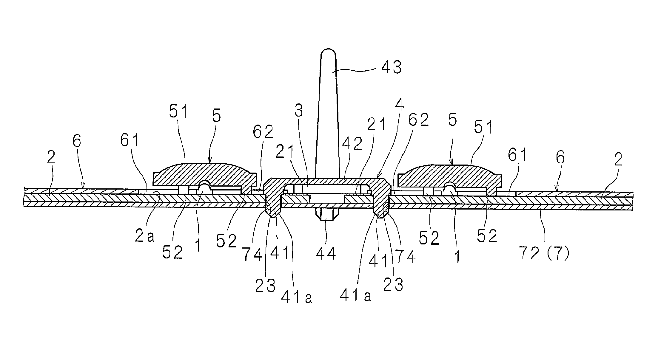
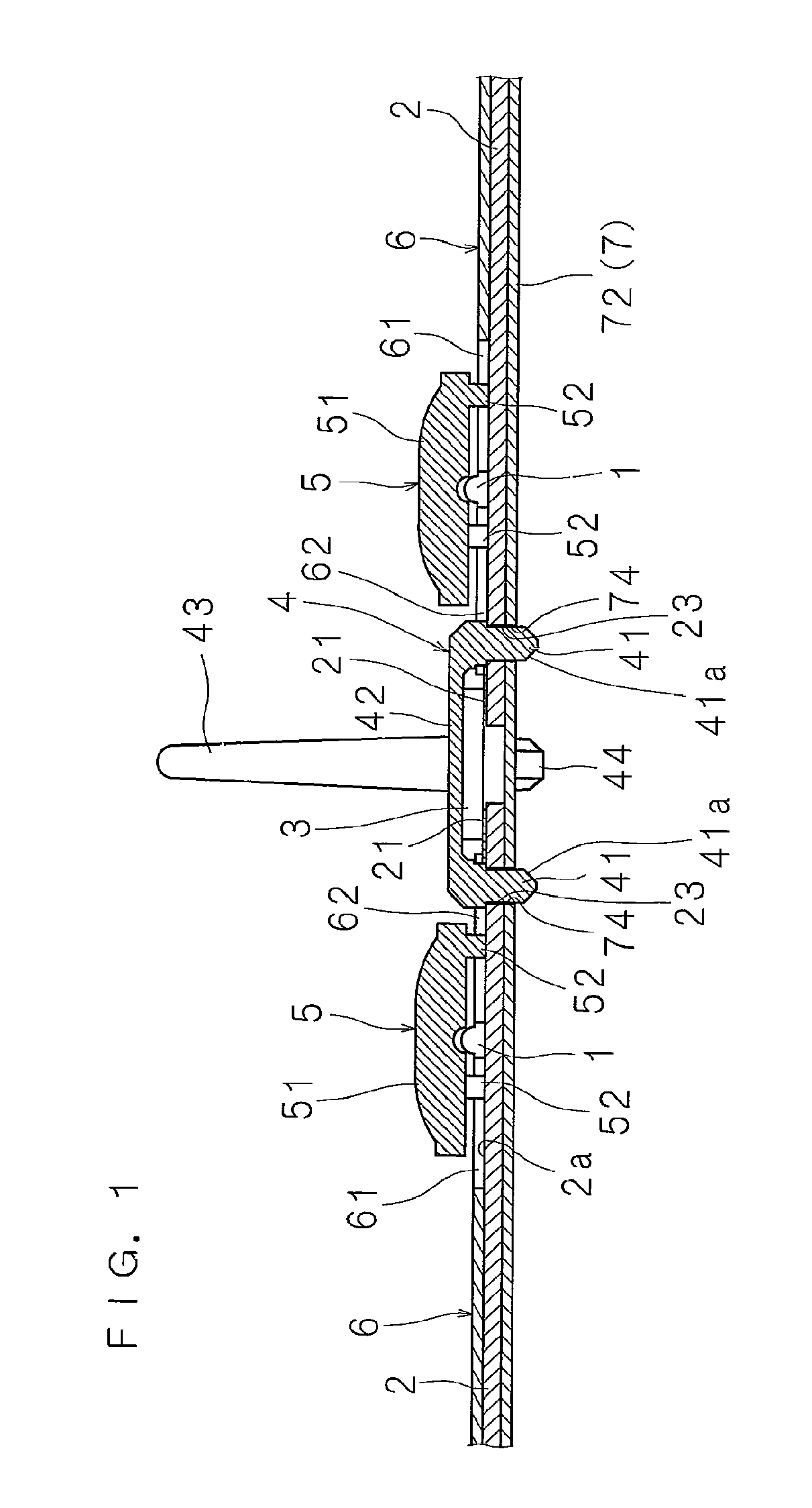
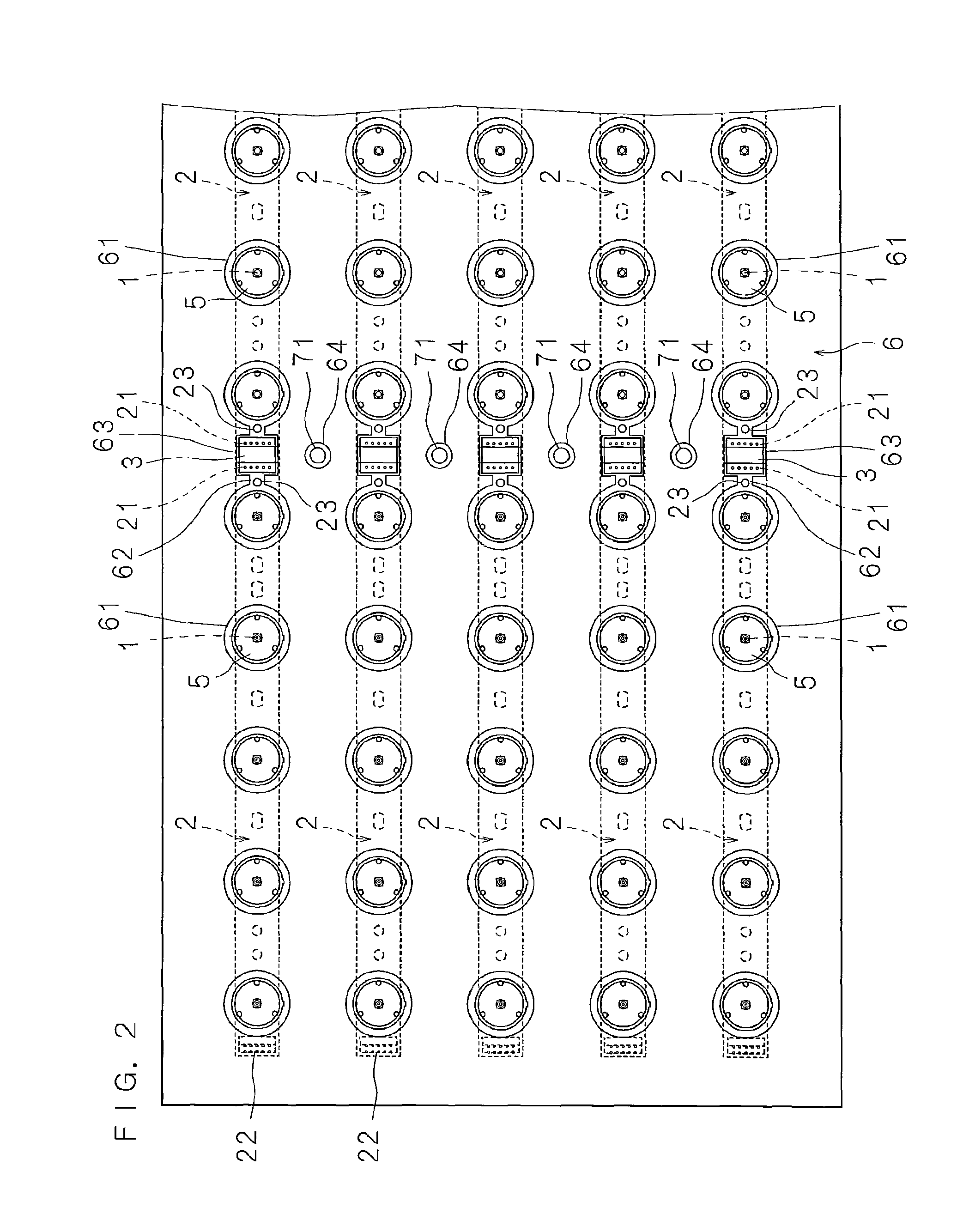
[0059]FIG. 1 is an enlarged cross-sectional view showing a part of the structure of an electronic device according to the present invention. FIG. 2 is a partly omitted plan view of the electronic device. FIG. 3 is a partly exploded schematic perspective view of the electronic device. FIG. 4 is a plan view showing a condition where a reflecting sheet is eliminated. FIG. 5 is a plan view showing a condition where the reflecting sheet is absent and a board holder is attached. FIG. 6 is an enlarged cross-sectional view taken along the line VI-VI of FIG. 5 in a condition where the reflecting sheet is present. FIG. 7 is an enlarged cross-sectional view taken along the line VII-VII of FIG. 5 in a condition where the reflecting sheet is present. FIG. 8 is a perspective view showing the structure of a light emitting diode board to which lenses are attached.
[0060]The shown electronic device is attached to the back side of a display section of a flat display apparatus having the display sectio...
second embodiment
[0085]This electronic device is structured so that, as shown in FIGS. 6 and 7, the connecting section 42 of the board holder 4 covers the connectors 3.
[0086]The board holder 4 is formed of a synthetic resin such as polycarbonate that is excellent in light reflectivity.
[0087]The coupling section 42 is formed in a length corresponding to the distance between the light emitting diode boards 2 in the outermost two rows and in a width wider than the connectors 3, faces the other surfaces of a plurality of connectors 3 connecting the adjacent light emitting diode boards 2 in a plurality of rows, and covers the connectors 3.
[0088]Since the connectors 3 normally are not white enough to have high reflectivity, if the connectors 3 are exposed, this causes brightness nonuniformity; however, in this electronic device, a plurality of connectors 3 connecting the adjacent light emitting diode boards 2 in a plurality of rows can be covered with the coupling section 42 that is excellent in light ref...
third embodiment
[0090]FIG. 10 is an enlarged cross-sectional view showing another structure of the relevant part of the electronic device. This electronic device is structured so that connectors 45 connected to the connecting sections 21, 21 of the adjacent light emitting diode boards 2, 2 are provided between the protruding sections 41, 41 of the coupling section 42 of the board holder 4 such that the connecting sections 21, 21 of the adjacent light emitting diode boards 2, 2 can be connected by the board holder 4.
[0091]The connectors 45 is formed of a conductive plate having: a fixed section 45a fixed to the coupling section 42 by fixing means such as an adhesive agent, coupling of concave and convex portions or riveting; and curved connecting sections 45b, 45b ranging on both ends of the fixed section 45a. The connectors 45 is structured so that when the protruding sections 41, 41 are inserted in the holes 23, 23, the connecting sections 45b, 45b are connected to the connecting sections 21, 21 o...
PUM
 Abstract
Description
Claims
Application Information
 - R&D
- Intellectual Property
- Life Sciences
- Materials
- Tech Scout
- Unparalleled Data Quality
- Higher Quality Content
- 60% Fewer Hallucinations
Browse by: Latest US Patents, China's latest patents, Technical Efficacy Thesaurus, Application Domain, Technology Topic, Popular Technical Reports.
© 2025 PatSnap. All rights reserved.Legal|Privacy policy|Modern Slavery Act Transparency Statement|Sitemap|About US| Contact US: help@patsnap.com


