Parallelized streaming accelerated data structure generation

a data structure and parallel stream technology, applied in the field of image processing, can solve the problems that current ray tracing techniques may not be able to take advantage of multiple core processors

Inactive Publication Date: 2014-04-08
IBM CORP
View PDF85 Cites 6 Cited by
  • Summary
  • Abstract
  • Description
  • Claims
  • Application Information

AI Technical Summary

Problems solved by technology

For this reason, current ray tracing techniques may not be able to take advantage of multiple core processors that can process many steps in parallel.

Method used


Image

  • Parallelized streaming accelerated data structure generation
  • Parallelized streaming accelerated data structure generation
  • Parallelized streaming accelerated data structure generation

Examples


Embodiment Construction

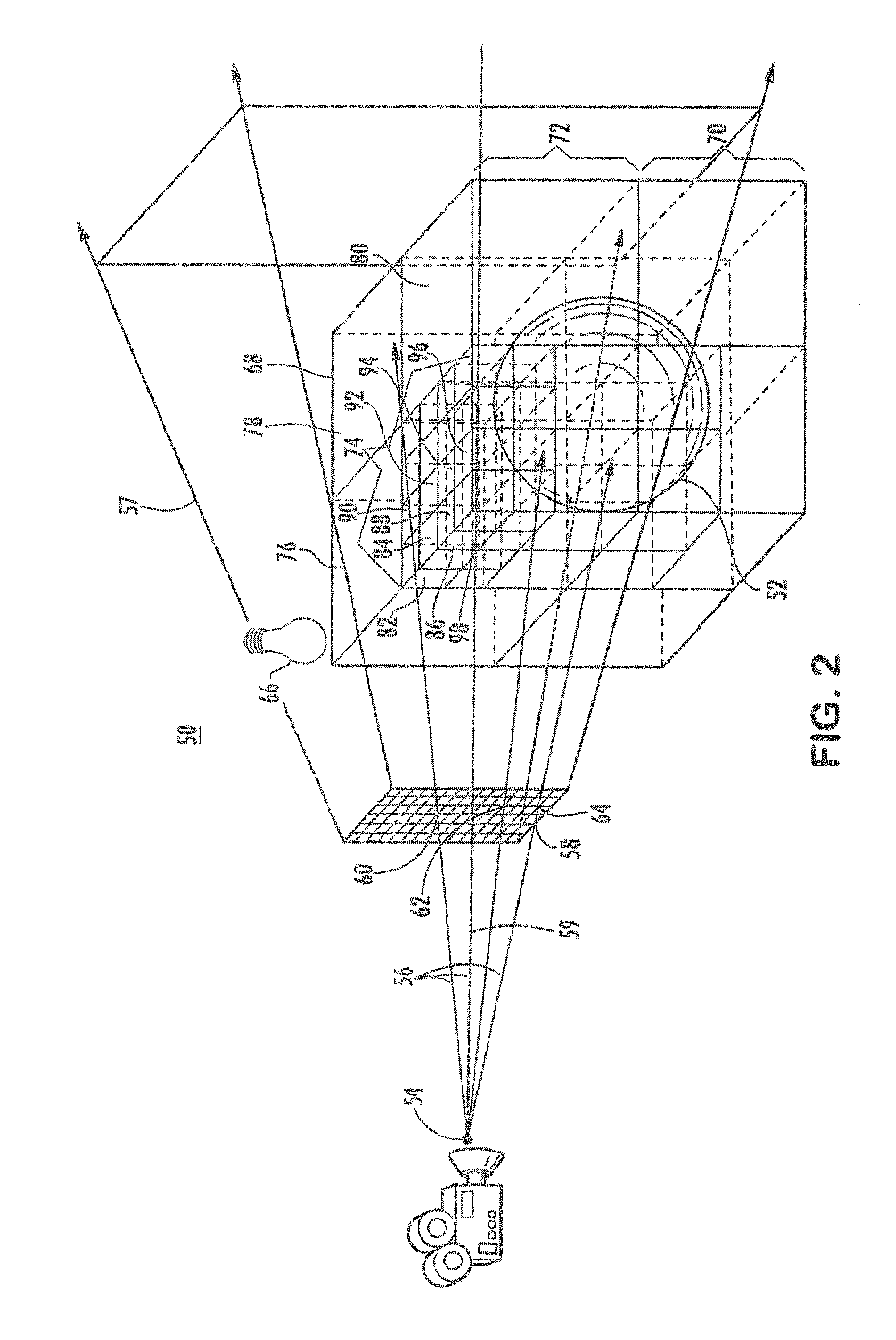
[0017]Ray tracing describes a technique for synthesizing photorealistic images by identifying and summing paths (“rays”) that connect light sources to a camera. In ray tracing, rays may be traced along a line of sight to determine visibility and may be traced from light sources to determine illumination. A ray may originate at a point in space described by a position vector and may travel along a direction vector. In ray tracing, to determine visibility, the ray may be sent from the origin along a line of sight described by the direction vector. The ray may be tested for intersection against objects within a three-dimensional image to determine the nearest visible object along that line of sight. Ray tracing may generate an image by tracing the ray through individual pixels of the objects in the three-dimensional image.

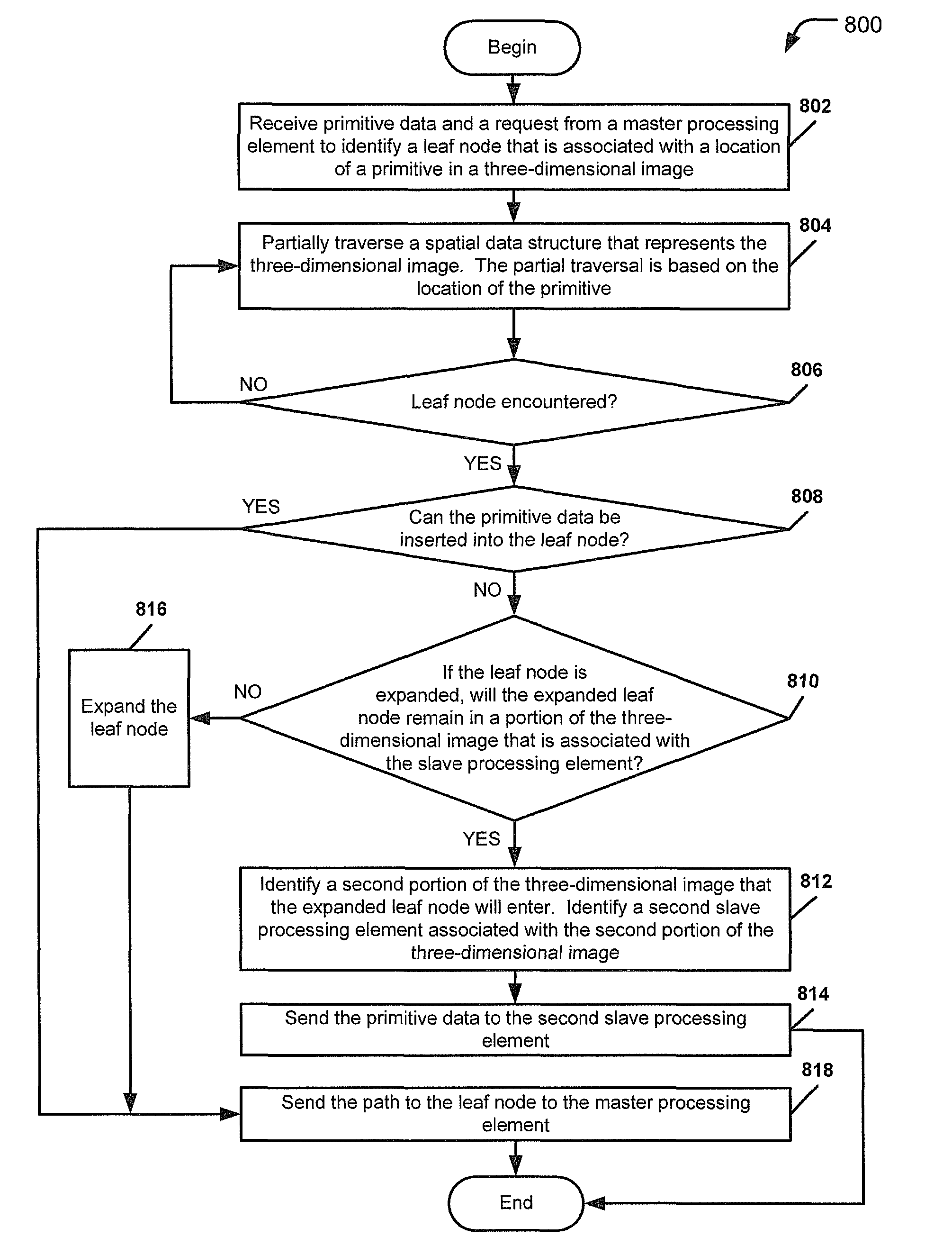
[0018]When rendering a three-dimensional image, a graphics system may initially create a spatial data structure that represents the three-dimensional image. The spati...


PUM


Abstract

A method includes receiving at a master processing element primitive data that includes properties of a primitive. The method includes partially traversing a spatial data structure that represents a three-dimensional image to identify an internal node of the spatial data structure. The internal node represents a portion of the three-dimensional image. The method also includes selecting a slave processing element from a plurality of slave processing elements. The selected processing element is associated with the internal node. The method further includes sending the primitive data to the selected slave processing element to traverse a portion of the spatial data structure to identify a leaf node of the spatial data structure.

Description

I. FIELD OF THE DISCLOSURE[0001]The present disclosure relates generally to image processing, and more specifically, to parallelized ray tracing of a three-dimensional image.II. BACKGROUND[0002]Ray tracing is a computer-based technique that may be used for creating photorealistic computer graphics in video game animation, motion pictures, and other media applications. In ray tracing, paths (“rays”) connecting light sources to objects are identified and summed. Rays are traced along a line of sight to determine visibility and from light sources to determine illumination.[0003]A ray generally originates at a point in space described by a position vector and travels along a direction vector. Ray tracing may be used to determine visibility by directing the ray from the origin along a line of sight described by the direction vector. The ray is tested for intersection against objects within a virtual scene to determine the nearest visible surface along that line of sight. Ray tracing can ...

Claims


Application Information

Patent Timeline
Patent Type & Authority Patents(United States)
IPC IPC(8): G09G5/00
CPCG06T15/06G06T2200/28G06T2210/52
Inventor MEJDRICH, ERIC O.SCHARDT, PAUL E.SHEARER, ROBERT A.TUBBS, MATTHEW R.
Owner IBM CORP
Why Eureka
Try Eureka