Light source apparatus and image pickup apparatus equipped with same
a technology of light source apparatus and image pickup, which is applied in the direction of lasers, laser details, instruments, etc., can solve the problems of narrowing the oscillation spectrum linewidth, unable to respond to applications in time, and obtaining short optical pulses
- Summary
- Abstract
- Description
- Claims
- Application Information
AI Technical Summary
Benefits of technology
Problems solved by technology
Method used
Image
Examples
first embodiment
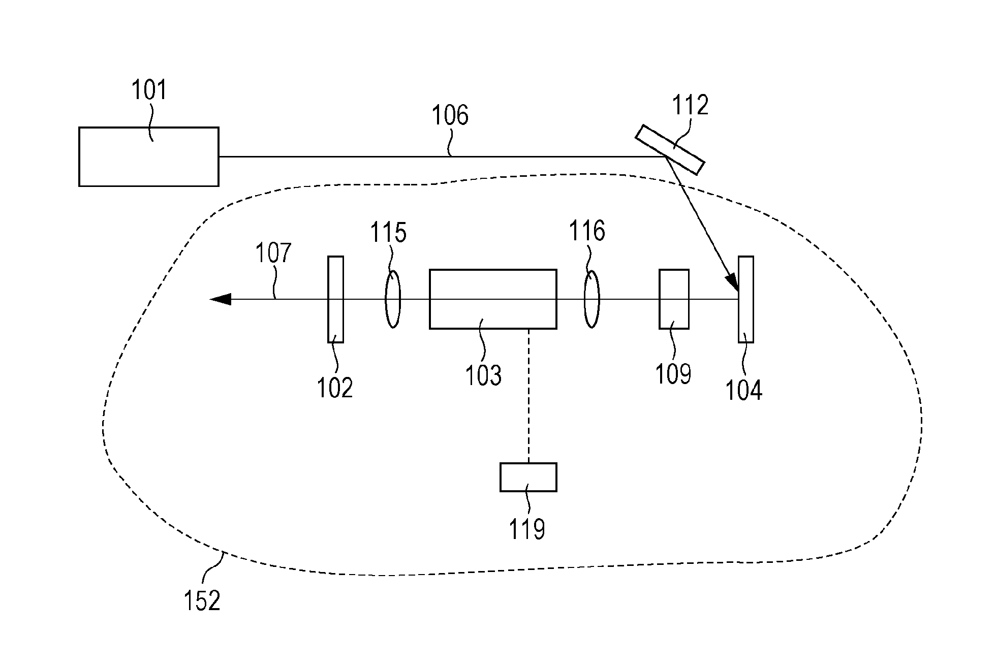
[0118]A light source apparatus according to a first embodiment will be described with reference to FIG. 9.
[0119]The light source apparatus illustrated in FIG. 9 includes a light irradiation source 101 and an optical resonator 152. The light irradiation source 101 is formed by a wavelength-tunable light source.
[0120]The optical resonator 152 includes a semiconductor optical amplifier serving as an optical amplification medium 103, an excitation source 119 that injects energy into the semiconductor optical amplifier, a reflective saturable absorber (mirror) 104, a gain flattening filter (GFF) 109, a partial reflection mirror 102, and light-collecting optics 115 and 116 that couple light in the resonator.
[0121]The operation of the light source apparatus of the first embodiment will be described below.
[0122]Irradiation light 106 emitted from the irradiation source (wavelength-tunable light source) 101 is an optical pulse train, and the center wavelength varies among pulses so that the i...
second embodiment
[0131]FIG. 10 illustrates the configuration of a light source apparatus according to a second embodiment.
[0132]A light source apparatus according to the second embodiment includes a wavelength-tunable light source 201 and a optical resonator 252 formed by a fiber optical system.
[0133]In the optical resonator 252, an optical pulse is introduced from the wavelength-tunable light source 201 into a ring type resonator through an isolator 218 and a coupler 214.
[0134]The introduced optical pulse passes through an isolator 208 and enters an optical amplifier 203, where the intensity thereof is amplified. The optical amplifier 203 is driven by a control device 229.
[0135]The amplified optical pulse passes through a circulator 215, is reflected by a saturable absorber mirror 204, and is returned to an optical fiber 202. Then, the optical pulse is taken out from the coupler 214, and is collimated by a collimator 219 to produce emergent light 207.
[0136]In the second embodiment, the optical reso...
third embodiment
[0145]An optical coherence tomographic (OCT) image pickup apparatus using a light source apparatus according to a third embodiment of the present invention will be described.
[0146]FIG. 17 illustrates the configuration of the OCT image pickup apparatus. The OCT image pickup apparatus illustrated in FIG. 17 basically includes a light source section (e.g., 1701), a specimen measuring section (e.g., 1707), a reference section (e.g., 1702), an interference section (1703), a light detecting section (e.g., 1709), and an image processing section (1711). The specimen measuring section irradiates a specimen with light from the light source section and transmits a reflected beam from the specimen. The reference section irradiates a reference mirror with light and transmits a reflected light beam from the reference mirror. The interference section causes the two reflected light beams to interfere with each other. The light detecting section detects interference light obtained from the interfere...
PUM
 Abstract
Description
Claims
Application Information
 - R&D
- Intellectual Property
- Life Sciences
- Materials
- Tech Scout
- Unparalleled Data Quality
- Higher Quality Content
- 60% Fewer Hallucinations
Browse by: Latest US Patents, China's latest patents, Technical Efficacy Thesaurus, Application Domain, Technology Topic, Popular Technical Reports.
© 2025 PatSnap. All rights reserved.Legal|Privacy policy|Modern Slavery Act Transparency Statement|Sitemap|About US| Contact US: help@patsnap.com


