
Light source apparatus and image pickup apparatus equipped with same

a technology of light source apparatus and image pickup, which is applied in the direction of lasers, laser details, instruments, etc., can solve the problems of narrowing the oscillation spectrum linewidth, unable to respond to applications in time, and obtaining short optical pulses

Inactive Publication Date: 2012-02-02
CANON KK
View PDF6 Cites 12 Cited by
  • Summary
  • Abstract
  • Description
  • Claims
  • Application Information

AI Technical Summary

Benefits of technology

[0019]The present invention provides a light source apparatus that can achieve a narrower oscillation spectrum linewidth and higher-speed wavelength sweeping.
[0023]The relationship (L<c / (nf)) between the optical resonator length L and the repetition frequency f of the optical pulse indicates a condition that mode locking is not caused by the optical pulse introduced from the wavelength-tunable light source into the optical resonator. This is an approach to an oscillating operation different from mode locking in which the oscillation spectral width (linewidth) is easy to increase.
[0025]Accordingly, the present invention can provide a light source apparatus that narrows the spectral width (linewidth) of the oscillation spectrum.

Problems solved by technology

Hence, this method cannot always sufficiently respond to applications that need a narrow spectral width.
However, this laser apparatus can obtain short optical pulses, but is not designed to narrow the oscillation spectrum linewidth.

Method used


Image

  • Light source apparatus and image pickup apparatus equipped with same
  • Light source apparatus and image pickup apparatus equipped with same
  • Light source apparatus and image pickup apparatus equipped with same

Examples


first embodiment

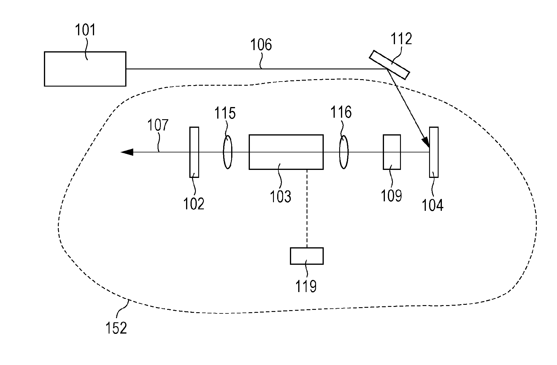
[0109]A light source apparatus according to a first embodiment will be described with reference to FIG. 9.

[0110]The light source apparatus illustrated in FIG. 9 includes a light irradiation source 101 and an optical resonator 152. The light irradiation source 101 is formed by a wavelength-tunable light source.

[0111]The optical resonator 152 includes a semiconductor optical amplifier serving as an optical amplification medium 103, an excitation source 119 that injects energy into the semiconductor optical amplifier, a reflective saturable absorber (mirror) 104, a gain flattening filter (GFF) 109, a partial reflection mirror 102, and light-collecting optics 115 and 116 that couple light in the resonator.

[0112]The operation of the light source apparatus of the first embodiment will be described below.

[0113]Irradiation light 106 emitted from the irradiation source (wavelength-tunable light source) 101 is an optical pulse train, and the center wavelength varies among pulses so that the i...

second embodiment

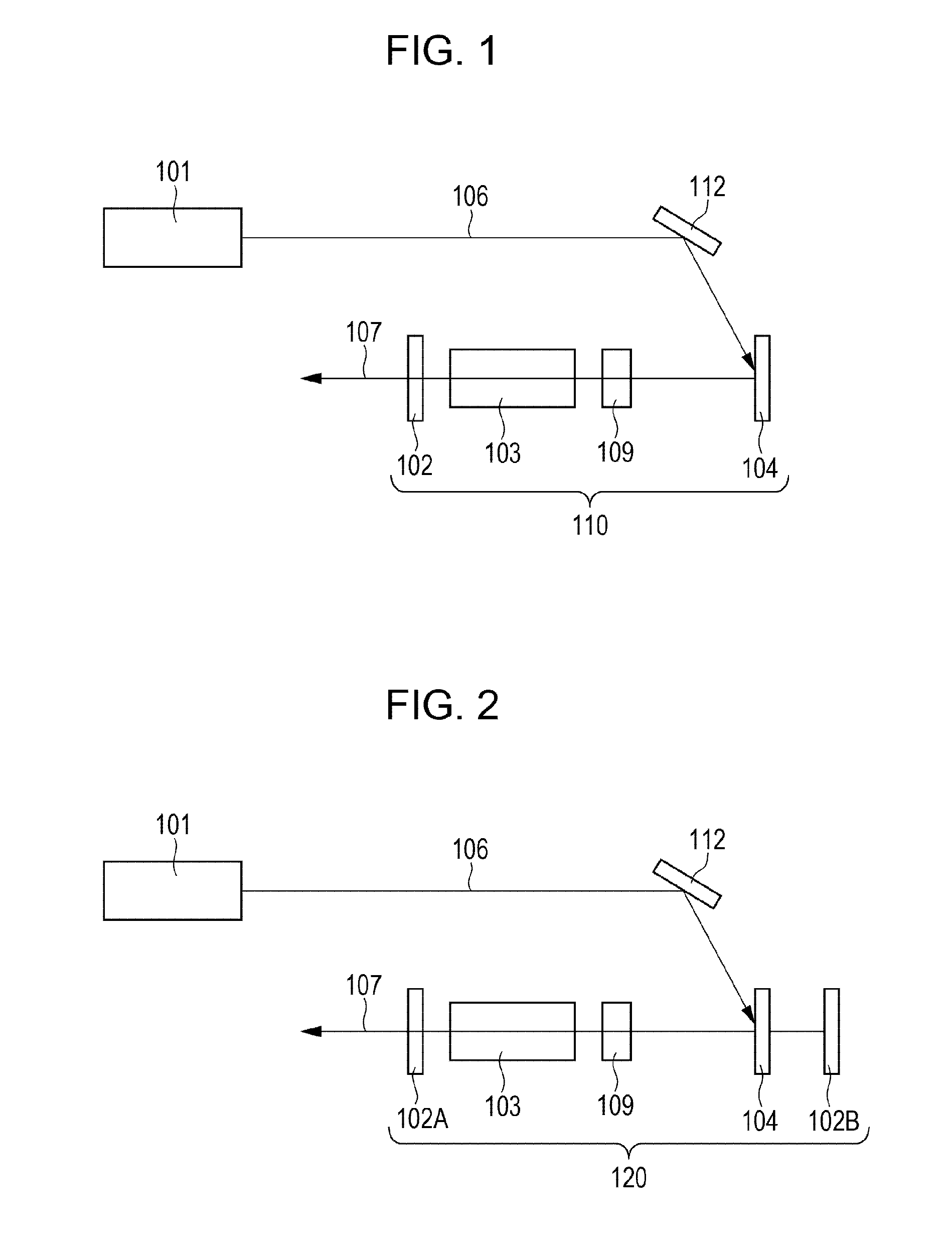
[0122]FIG. 10 illustrates the configuration of a light source apparatus according to a second embodiment.

[0123]A light source apparatus according to the second embodiment includes a wavelength-tunable light source 201 and a optical resonator 252 formed by a fiber optical system.

[0124]In the optical resonator 252, an optical pulse is introduced from the wavelength-tunable light source 201 into a ring type resonator through an isolator 218 and a coupler 214.

[0125]The introduced optical pulse passes through an isolator 208 and enters an optical amplifier 203, where the intensity thereof is amplified. The optical amplifier 203 is driven by a control device 229.

[0126]The amplified optical pulse passes through a circulator 215, is reflected by a saturable absorber mirror 204, and is returned to an optical fiber 202. Then, the optical pulse is taken out from the coupler 214, and is collimated by a collimator 219 to produce emergent light 207.

[0127]In the second embodiment, the optical reso...

third embodiment

[0136]An optical coherence tomographic (OCT) image pickup apparatus using a light source apparatus according to a third embodiment of the present invention will be described.

[0137]FIG. 17 illustrates the configuration of the OCT image pickup apparatus. The OCT image pickup apparatus illustrated in FIG. 17 basically includes a light source section (e.g., 1701), a specimen measuring section (e.g., 1707), a reference section (e.g., 1702), an interference section (1703), a light detecting section (e.g., 1709), and an image processing section (1711). The specimen measuring section irradiates a specimen with light from the light source section and transmits a reflected beam from the specimen. The reference section irradiates a reference mirror with light and transmits a reflected light beam from the reference mirror. The interference section causes the two reflected light beams to interfere with each other. The light detecting section detects interference light obtained from the interfere...


PUM


Abstract

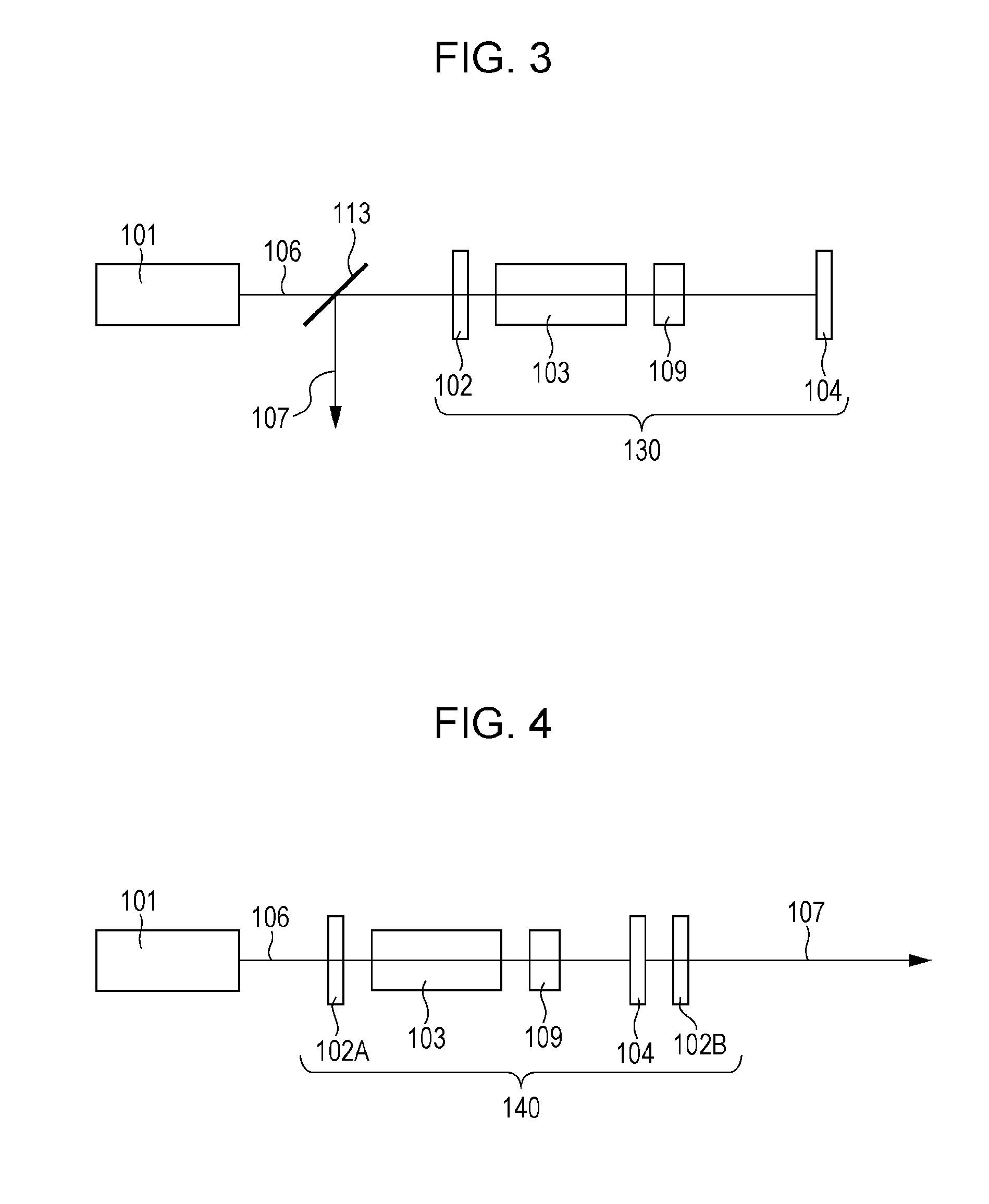
A light source apparatus includes an optical resonator formed by an optical amplification medium and an optical switch. The optical switch includes a saturable absorber and changes its transmittance or reflectance when receiving an optical pulse emitted from a light irradiation source which includes a wavelength-tunable light source. The light source apparatus emits amplified light from the optical resonator in correspondence with the center wavelength of the optical pulse from the wavelength-tunable light source. The relationship between a length L and an effective refractive index n of the optical resonator and a repetition frequency f of the optical pulse satisfies a condition L<c / (nf), and a relationship between the length L and a recovery time τ in which the changed transmittance or reflectance of the optical switch recovers satisfies a condition τ>(nL) / c.

Description

BACKGROUND OF THE INVENTION[0001]1. Field of the Invention[0002]The present invention relates to a light source apparatus that can change the oscillation wavelength and an image pickup apparatus using the light source apparatus.[0003]2. Description of the Related Art[0004]Various light sources, especially, laser light sources that can change the oscillation wavelength have been used in the fields of communication networks and inspection apparatuses.[0005]There are demands for high-speed wavelength switching in the field of communication networks and high-speed and wide-range wavelength sweeping in the field of inspection apparatuses.[0006]Examples of inspection apparatuses to which wavelength-tunable (sweep) light sources are applicable are a laser spectroscope, a dispersion measuring apparatus, a film-thickness measuring apparatus, and a swept source optical coherence tomography (SS-OCT) apparatus, among others.[0007]Optical coherence tomography (OCT) is an imaging technique in whi...

Claims


Application Information

Patent Timeline
IPC IPC(8): G01B9/02H01S3/113H01S3/10
CPCH01S3/06791H01S3/08004H01S3/08059H01S3/10084G01B9/02091H01S5/50H01S2301/04G01B9/02004H01S3/113
Inventor YAMADA, TOMOHIRO
Owner CANON KK
Learn More