Dual hydraulic power steering system

Inactive Publication Date: 2014-04-15
R H SHEPPARD
View PDF10 Cites 55 Cited by
  • Summary
  • Abstract
  • Description
  • Claims
  • Application Information

AI Technical Summary

Benefits of technology

[0008]The disclosed hydraulic power steering system has other advantages. The system utilizes time-tested and reliable hydraulic components that are readily modified for use in the improved dual steering wheel system. Because the two steering wheels are not mechanically linked on the input side

Problems solved by technology

The miter gears and related bearings generate friction that impairs steering feel, an

Method used


Image

  • Dual hydraulic power steering system
  • Dual hydraulic power steering system
  • Dual hydraulic power steering system

Examples


Embodiment Construction

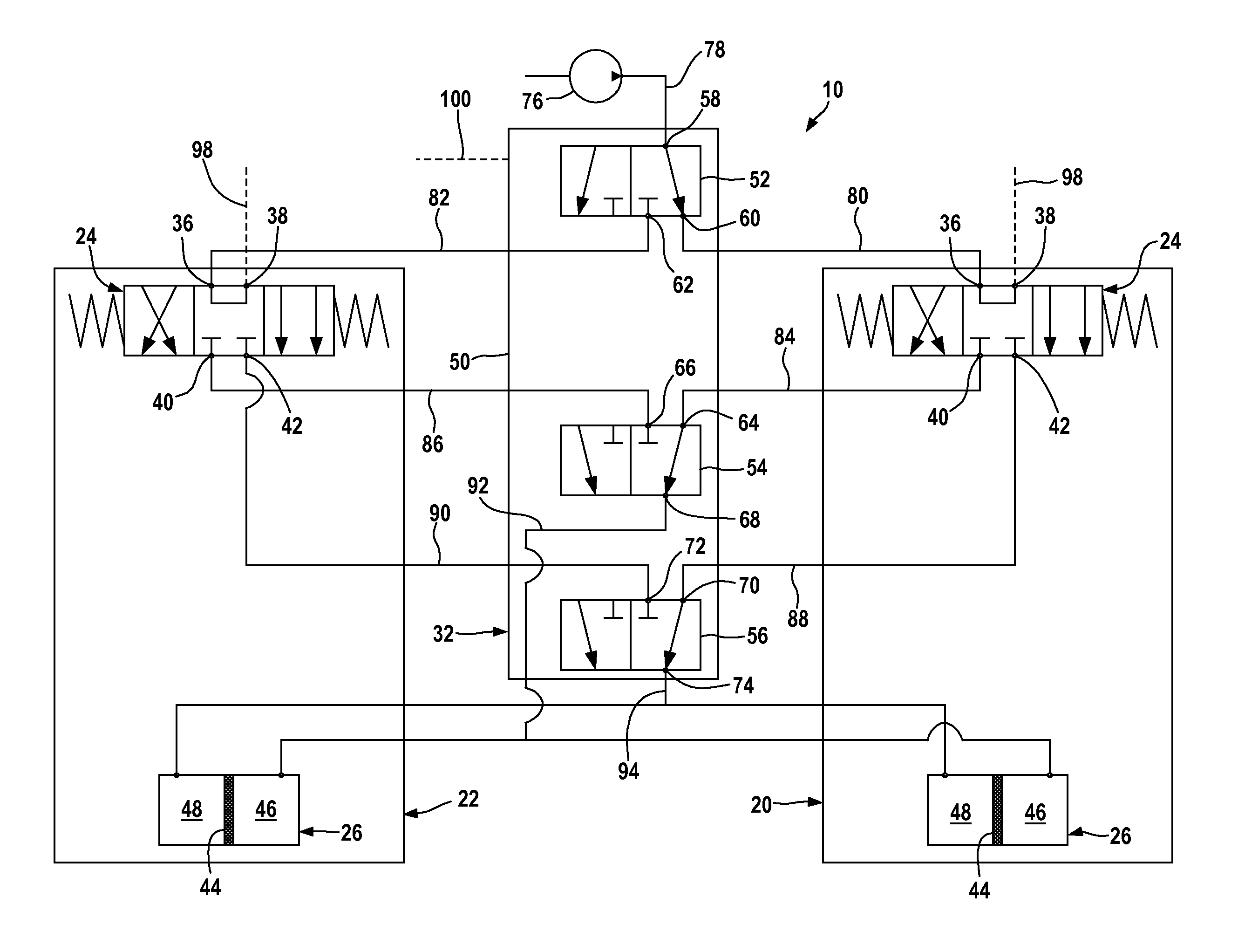
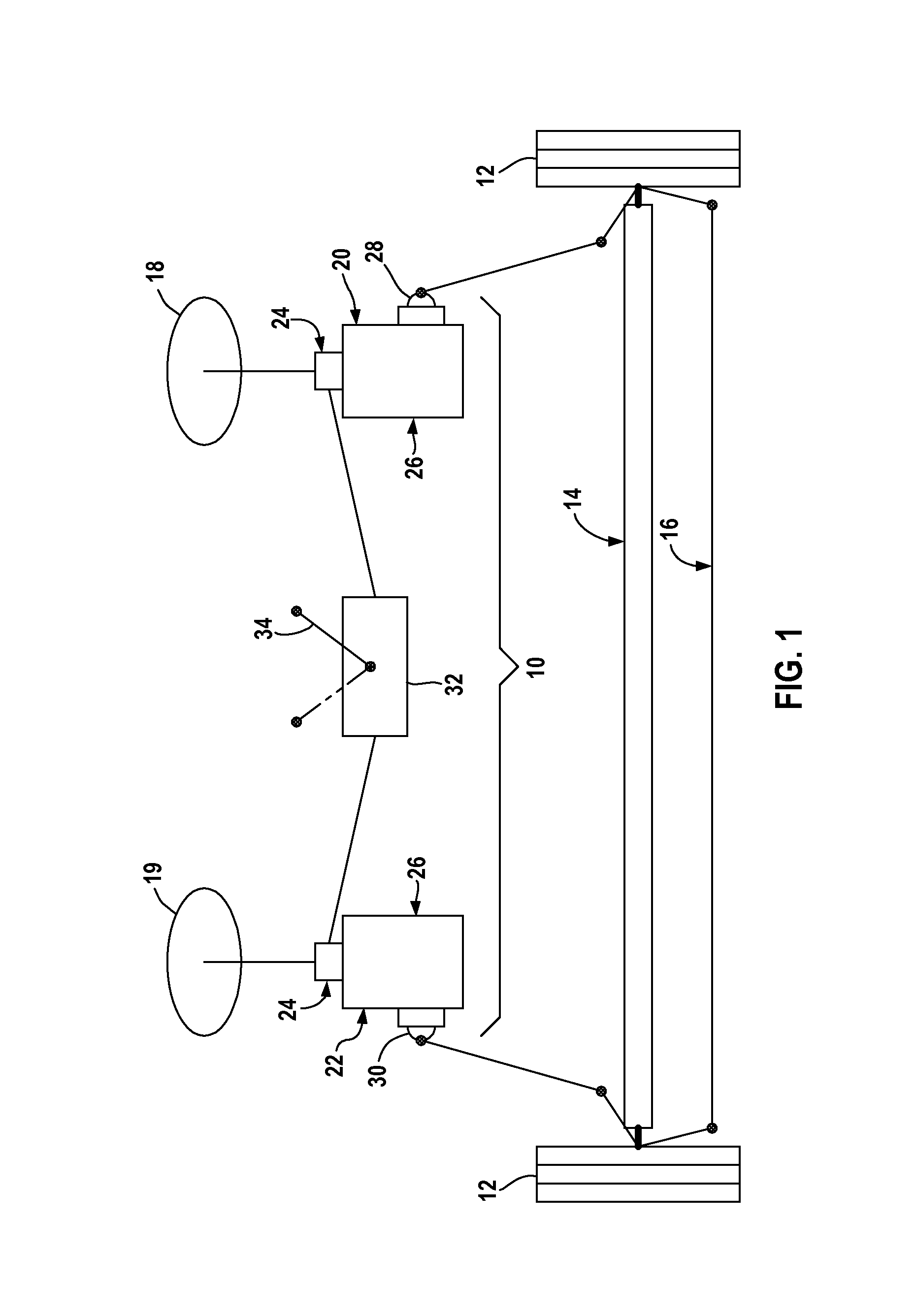
[0016]FIG. 1 schematically illustrates a hydraulic power steering system 10. The power steering system 10 drives the steerable wheels 12 of a motor vehicle 14 via a steering linkage 16. The motor vehicle 14 includes a right-side steering wheel 18 and a left-side steering wheel 19. The right-side steering wheel 18 is operatively connected to an integral steering gear 20 and the left-side steering wheel 19 is operatively connected to an integral steering gear 22, the steering gears 20, 22 forming part of the steering system 10. Each steering gear 20, 22 has a control valve 24 and a fluid motor 26, the control valve 24 connected to the steering wheel 18. The fluid motor 26 of each respective steering gear 20, 22 drives a respective Pitman arm 28, 30 connected to the vehicle steering linkage 16.

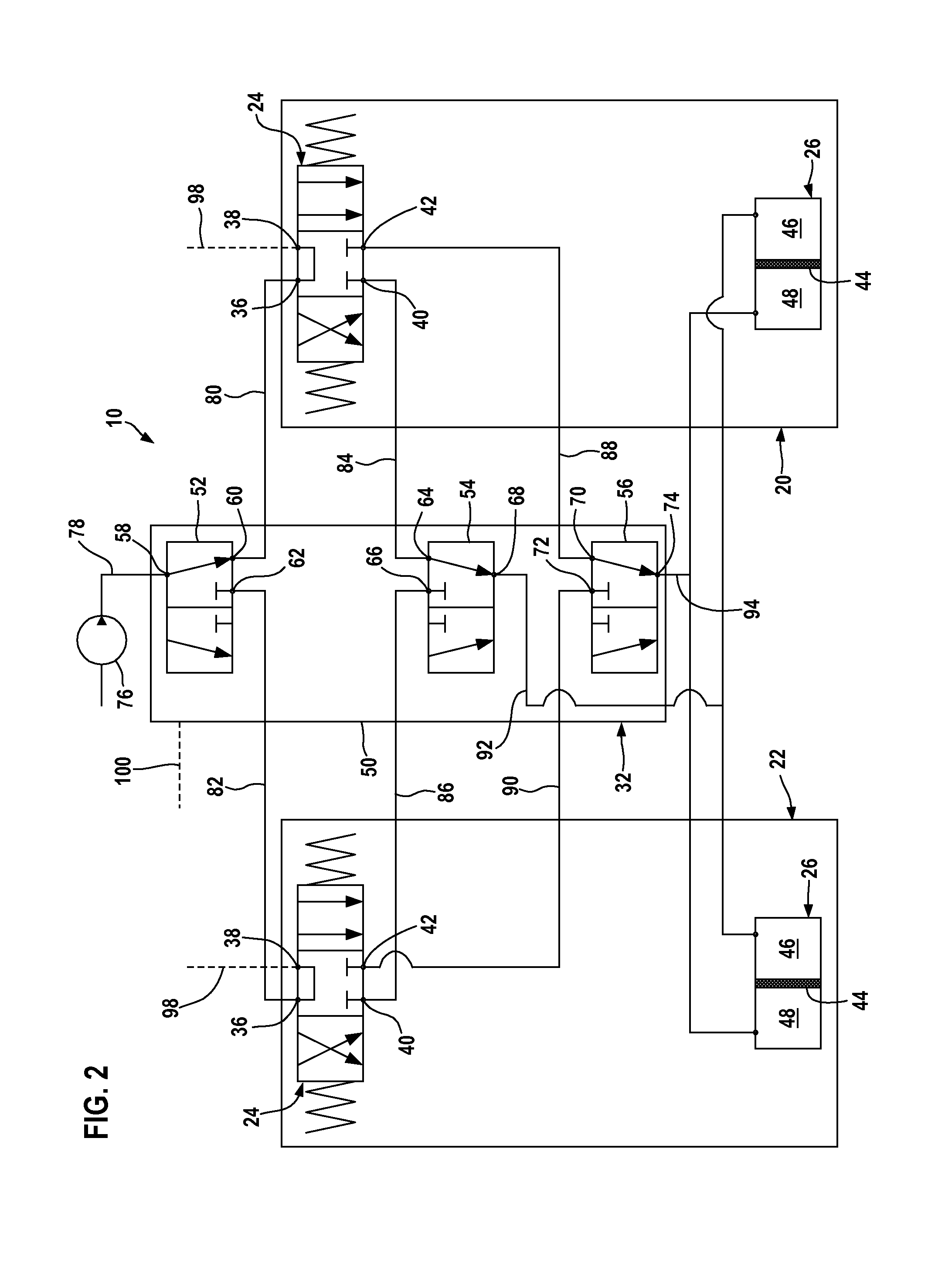
[0017]The hydraulic assembly 10 further includes a valve assembly 32 that selectively flows high-pressure fluid to the control valve 24 of either the steering gear 20 or of the power steering gea...


PUM


Abstract

A hydraulic power steering system controllable by left and right steering wheels has two control valves, each valve connected to a respective left and right steering wheel, and a valve arrangement that selectively connects one control valve to a source of high-pressure fluid and disconnects the other control valve from the source of high-pressure fluid.

Description

FIELD OF THE DISCLOSURE[0001]This disclosure relates to hydraulic power steering systems for motor vehicles, and in particular to power steering systems controlled by two steering wheels for steering the vehicle from either the left or right side of the vehicle.BACKGROUND OF THE DISCLOSURE[0002]Heavy duty motor vehicles include a hydraulic power steering system in which the wheels of the steering axle of the vehicle are steered by turning a steering wheel operatively connected to a fluid motor. Turning the steering wheel operates a control valve that directs the flow of high-pressure fluid supplied from a pump or accumulator to the fluid motor and drives the motor piston. Piston movement drives an output member, such as a Pitman arm, connected to a steering linkage that in turn drives the wheels towards or away from their centered positions.[0003]Customers of some heavy-duty motor vehicles, such as refuse trucks, often require that the truck have dual steering wheels that enable ste...

Claims


Application Information

Patent Timeline
IPC IPC(8): B62D5/00
CPCB62D1/22B62D5/06
Inventor HAMMOND, ROBERT WILLIAMTIPTON, JEFFREY EDWARD
Owner R H SHEPPARD
Why Eureka
Try Eureka