
Method of manipulating impedance plane with a multi-point touch on touch screen

a multi-point touch and touch screen technology, applied in the field of methods, can solve the problems of time-consuming operation and require additional care, and achieve the effect of enhancing user experience and simplifying and more intuitive operation

Active Publication Date: 2014-04-15
OLYMPUS NDT
View PDF8 Cites 3 Cited by
  • Summary
  • Abstract
  • Description
  • Claims
  • Application Information

AI Technical Summary

Benefits of technology

The invention is a multi-point touch screen that allows users to interact with signals using fewer steps. This provides a more intuitive experience as users can control or adjust signals with their hand. The technical effect of the invention is to make it easier for users to work with the signals, improving the user experience.

Problems solved by technology

This operation can become time consuming as the user needs to go through the whole sequence before each new inspection procedure (sometimes twice for a dual frequency setup).
Another limitation of the current method is the troublesome interaction between some parameters such as vertical gain and rotation, which require some additional care when instruments settings are defined.
More specifically, some additional drawbacks involved in a typical prior art portable eddy current instrument featuring an eddy current impedance plane that shows signal produced by scanning a defect with a probe and the controls available for manipulating this impedance plane signal to enhance the detectability of defect signal over noise signal, are as follows.

Method used


Image

  • Method of manipulating impedance plane with a multi-point touch on touch screen
  • Method of manipulating impedance plane with a multi-point touch on touch screen
  • Method of manipulating impedance plane with a multi-point touch on touch screen

Examples


Embodiment Construction

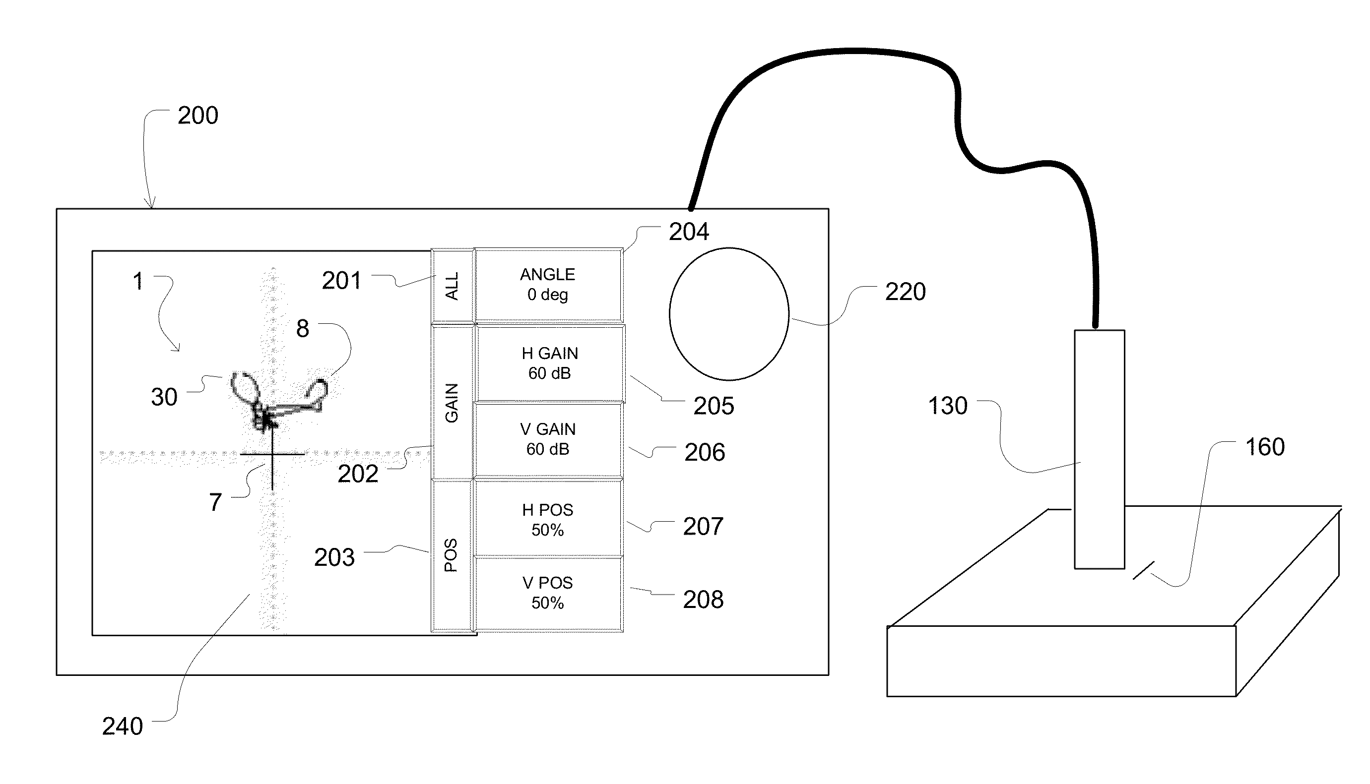
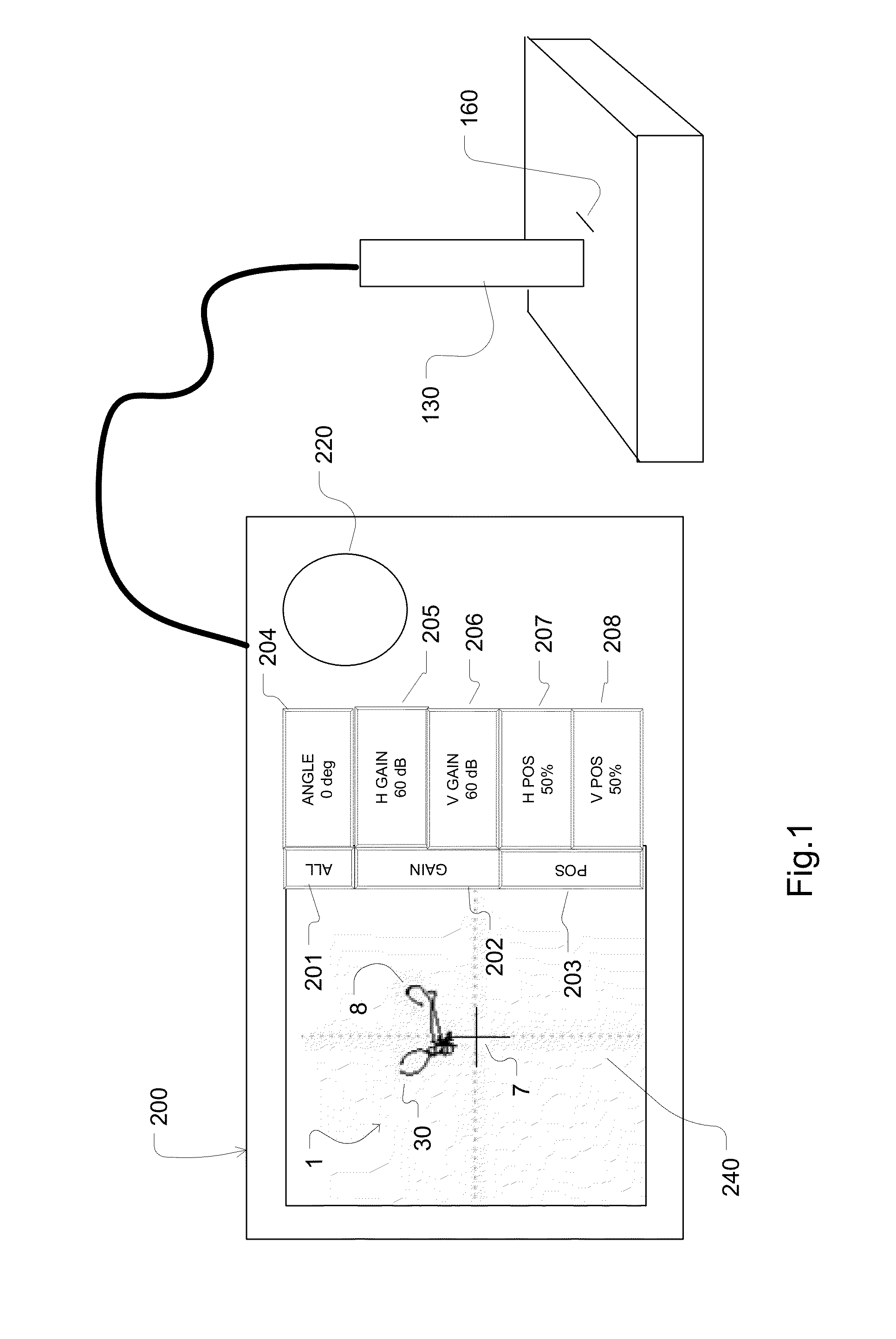
[0029]FIG. 1 is a first overview of an instrument 200 built in accordance with an aspect of teachings of this invention using a multi-point touch screen interface 240 and displaying the impedance plane 1 for representing the impedance plane signal 8 and displaying a set of buttons 201, 202, 203, 204, 205, 206, 207 and 208.

[0030]A benefit of the use of a touch screen is the integration of the buttons and displayed parameters to provide the user with a set of buttons 201, 202, 203, 204, 205, 206, 207 and 208. According to an aspect of the invention, a touch screen interface provides the user with the ability to manipulate impedance plane signal 8 without using knob 220 (although 220 can still be used for some precise operations). They may also have ability to modify simultaneously many parameters of the impedance plane with a single touch screen operation.

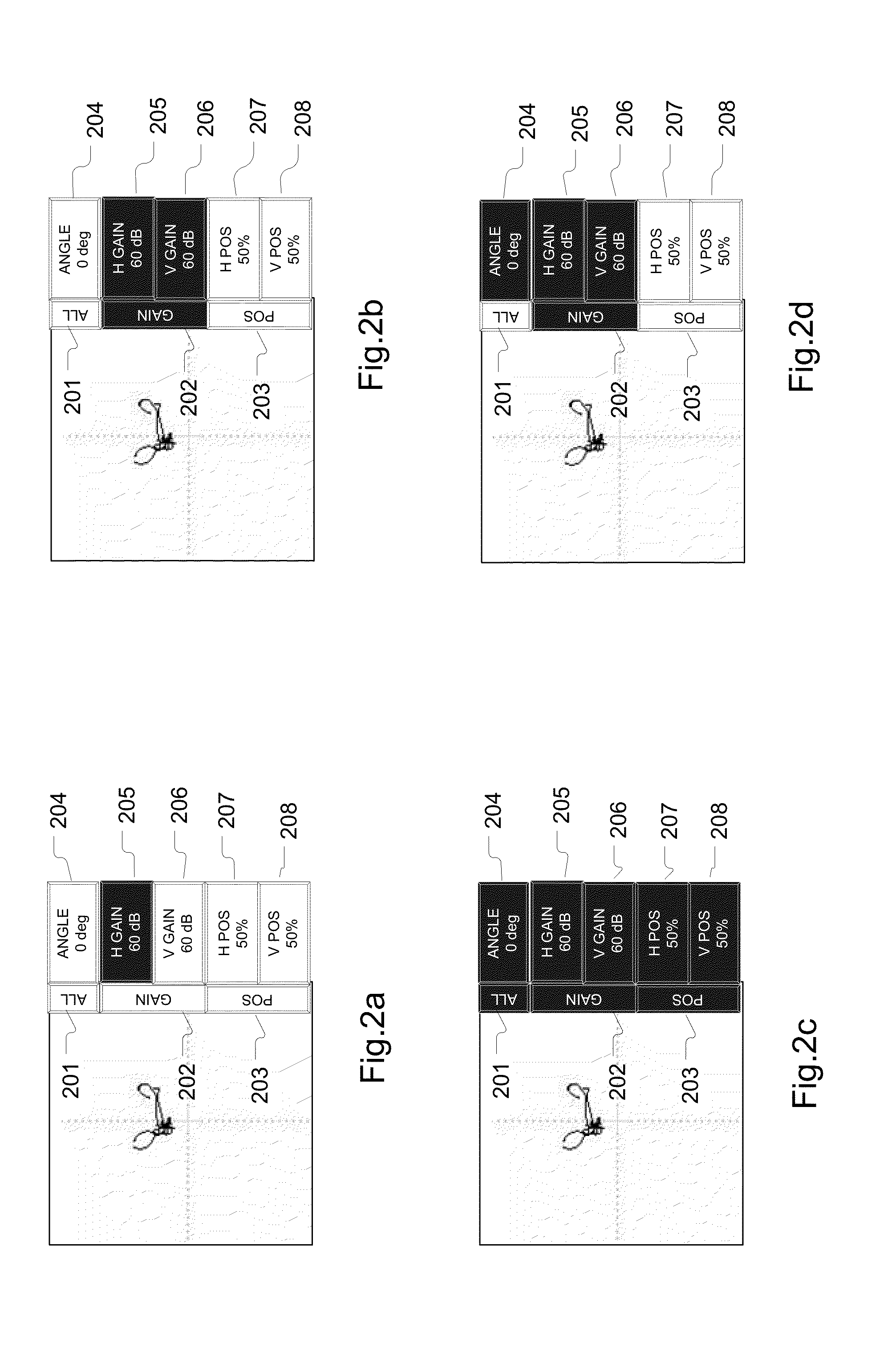
[0031]FIG. 2a shows how parameters to be modified are first selected on the touch screen interface. Buttons 204 (rotation angle), 2...


PUM


Abstract

A touch screen is disclosed which responds to a user's touch for re-drawing, re-scaling, re-translating and re-positioning an impedance plane signal received from non-destructive testing equipment, such as an eddy current sensor. The impedance plane is manipulated by slidingne, two or more fingers simultaneously to an end position to effectuate a complete re-drawing operation of the image.

Description

FIELD OF THE INVENTION[0001]The present invention relates to non-destructive testing and inspection systems (NDT / NDI), using more specifically Eddy Current Technology (ECT), Eddy Current Array technology (ECA), Pitch-Catch Bond Testing (PCBT) and Resonance Bond-Testing (RBT).BACKGROUND OF THE INVENTION[0002]Eddy current inspection is commonly used as non-destructive control to detect flaws in surfaces of manufactured components fabricated from a conductive material, such as bars, tubes, and special parts for the automotive, aeronautic or energy industries.[0003]Since the 1950's, eddy current instruments render test information on an impedance plane display. The original concept of the impedance plane display was to divide the detector coil impedance into resistive and reactive components to produce bi-dimensional figures yielding significant information on the inspected component. The concept quickly evolved as users understood the value of manipulating the impedance plane to highli...

Claims


Application Information

Patent Timeline
Patent Type & Authority Patents(United States)
IPC IPC(8): G06F3/045
CPCG06F3/04883G06F2203/04808G01N27/90G06F3/04845G06F3/04847
Inventor HABERMEHL, JASONLEPAGE, BENOITBOURGELAS, TOMMY
Owner OLYMPUS NDT
Learn More