

Roll stand provided with a displacement device
- Summary
- Abstract
- Description
- Claims
- Application Information
AI Technical Summary
Benefits of technology
Problems solved by technology
Method used
Image

Examples
Embodiment Construction
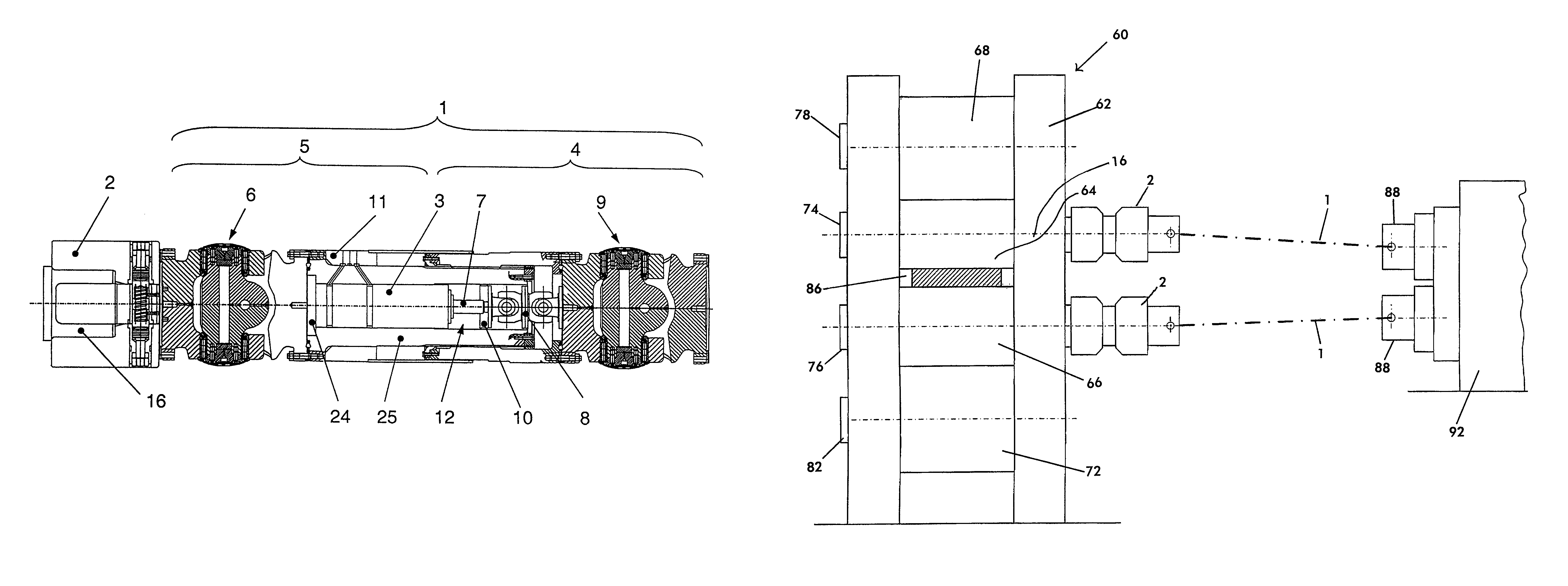
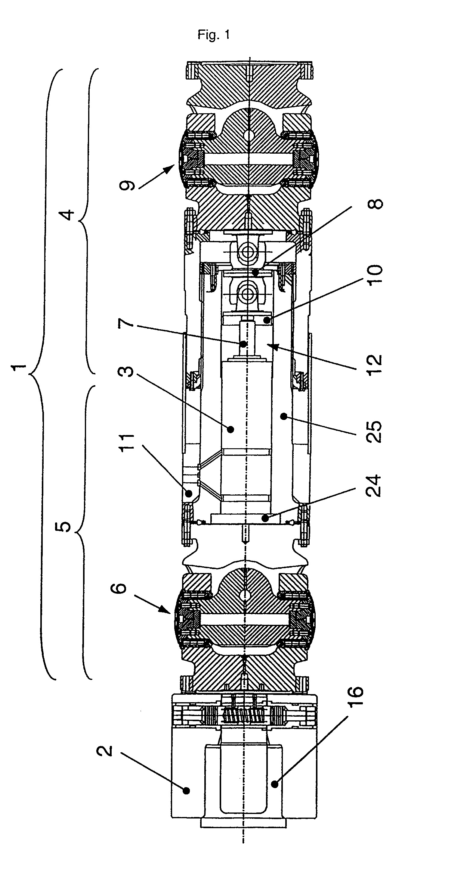
[0039]FIG. 1 illustrates, in the form of a detail, the drive shaft (1) with the two shaft parts (4) and (5). The shaft part (4) is arranged on the motor side and fixedly, while the shaft part (5) is arranged movably in the axial direction. The drive shaft (1) serves for driving a roll, while height displacements and axial position changes can be compensated correspondingly by means of the drive shaft (1). The shaft (1) illustrated has two joint heads (6, 9). A piston / cylinder unit (3) for the axial displacement of the movable shaft part (5) is arranged in a recess (12), the cylinder being fixed between the joint head (6) and the drive shaft inner part (25) by means of a cylinder flange (24). The piston rod (7) is guided in the radial direction in the drive shaft inner part (25) by means of a guide disk (10). The piston rod (7) is connected to the joint head (9) via the guide disk (10) and a connecting joint (8), while unavoidable axial displacements can be compensated and therefore ...
PUM
| Property | Measurement | Unit |
|---|---|---|
| Force | aaaaa | aaaaa |
| Length | aaaaa | aaaaa |
| Torque | aaaaa | aaaaa |
Abstract
Description
Claims
Application Information