
Inverted miniature relay

A relay and flip-chip technology, applied in the direction of relays, electromagnetic relays, detailed information of electromagnetic relays, etc., can solve the problems of increased manufacturing cost, economy, poor stability and reliability, insufficient elastic pressure, etc., to ensure stability and Reliability, improve the anti-drop performance, and eliminate the effect of poor stability

Pending Publication Date: 2019-11-22
SICHUAN HONGFA ELECTROACOUSTIC
View PDF1 Cites 0 Cited by
  • Summary
  • Abstract
  • Description
  • Claims
  • Application Information

AI Technical Summary

Problems solved by technology

[0004] The above-mentioned typical "sugar cube" type relay mainly has the following technical problems, which make its economy, stability and reliability poor:
[0005] 1. The moving spring assembly and the static spring assembly span half of the magnetic circuit, making the paths longer. On the one hand, it will lead to more materials used in manufacturing, which will increase the manufacturing cost. On the other hand, it will make the conductive distance long and the internal resistance large. , it is difficult to meet the technical requirements of large loads;
[0006] 2. The static spring assembly extends from the bottom of the coil frame through the coil window to the top of the coil frame, and the creepage distance between it and the coil is relatively low, which is prone to electric shock during use and has low safety performance;
[0007] 3. The armature is assembled on the knife edge of the yoke through the elastic pressure of the moving spring assembly. Once the moving reed of the moving spring assembly is fatigued and the elastic force is slightly damaged, the elasticity of the assembly between the armature and the yoke will be reduced. If the pressure is insufficient, the matching structure of the armature on the yoke cannot be maintained stably, and the armature is easy to shift, which will cause the relay to work abnormally or fail prematurely
Although this technology reduces the manufacturing cost and meets the technical requirements of large loads with a specific flip-chip structure, its armature is still assembled on the edge of the yoke through the elastic pressure of the moving spring assembly, which makes the above-mentioned typical The third technical problem of the "sugar cube" type relay still exists - that is, once the moving reed of the moving spring assembly is fatigued and the elastic force is slightly damaged, the elastic pressure of the assembly between the armature and the yoke will be insufficient. The matching structure of the armature on the yoke cannot be maintained stably, and the armature is easy to shift, which will cause the relay to work abnormally or fail early, and the service life is short

Method used


Image

  • Inverted miniature relay
  • Inverted miniature relay
  • Inverted miniature relay

Examples


Embodiment 1

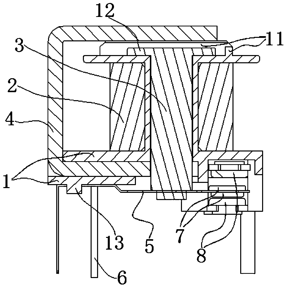
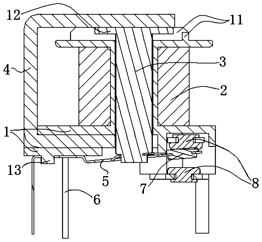
[0037] see figure 2 , image 3 , Figure 4 , Figure 5 and Figure 6 As shown, the present invention includes a bobbin 1, an iron core 3, a yoke 4, a moving spring assembly and a static spring assembly.

[0038] Among them, the coil frame 1 is a cylindrical structure with the top and bottom ends turned outward respectively, and the axial hollow of the coil frame 1 forms an iron core assembly hole. structure. A coil 2 (usually an enameled coil) is assembled in the space between the top end and the bottom end of the coil frame 1 . The bottom of the coil frame 1 is provided with a coil pin 6 connected with the coil 2 and extending outward. One side of the bottom of the bobbin 1 is provided with a radially extending insertion slot 10, the insertion slot 10 goes straight from one side of the bottom of the coil bobbin 1 to the assembly hole of the iron core, and the insertion slot 10 is a straight slot structure (specifically See figure 2 , image 3 and Figure 4 shown);...

Embodiment 2

[0047] The invention includes a coil frame, an iron core, a yoke, a moving spring assembly and a static spring assembly.

[0048] Wherein, the bobbin is a cylindrical structure whose top and bottom ends are turned outward respectively, and the axial hollow of the bobbin forms an iron core assembly hole. A coil (usually an enameled coil) is fitted in the space between the top and bottom ends of the bobbin. The bottom of the coil frame is provided with coil pins connected with the coil and extending outward. One side of the bottom of the coil frame is provided with a radially extending insertion slot, which goes straight from one side of the bottom of the coil frame to the assembly hole of the iron core, and the insertion slot is a straight slot structure; the iron core on the top of the coil frame There are three reinforcing ribs protruding upwards on the outer periphery of the assembly hole. These three reinforcing ribs enclose a space with one side opening on the top of the ...

Embodiment 3

[0057] The invention includes a coil frame, an iron core, a yoke, a moving spring assembly and a static spring assembly.

[0058]Wherein, the bobbin is a cylindrical structure whose top and bottom ends are turned outward respectively, and the axial hollow of the bobbin forms an iron core assembly hole. A coil (usually an enameled coil) is fitted in the space between the top and bottom ends of the bobbin. The bottom of the coil frame is provided with coil pins connected with the coil and extending outward. One side of the bottom of the bobbin is provided with a radially extending insertion slot, which goes straight from one side of the bottom of the bobbin to the assembly hole of the iron core, and the insertion slot is a straight slot structure. In addition, the bottom surface of the bottom of the coil frame is provided with an assembly structure of a moving spring assembly and an assembly structure of a static spring assembly.

[0059] The moving spring assembly is mainly c...


PUM


Abstract

The invention discloses an inverted type small relay. The electromagnetic relay comprises a coil rack, an iron core, a yoke, a movable spring assembly and a static spring assembly, a coil is assembledon the coil rack; the movable spring assembly and the static spring assembly are respectively assembled at the bottom of the coil rack, and the movable spring contact and the static spring contact are correspondingly matched; the iron core is axially assembled in the coil rack in a manner that the two ends of the iron core can extend out of the corresponding end parts of the coil rack; the bottomend of the iron core is connected with a movable contact spring of the movable contact spring assembly, the bottom of the yoke is assembled at the bottom of the coil frame, the top of the yoke extends to the position above the top of the coil frame, and the top of the yoke is located above the top end of the iron core so as to form a moving space of the iron core in the axial direction. The invention has the characteristics of simple structure, low manufacturing cost, stable performance, long service life and the like.

Description

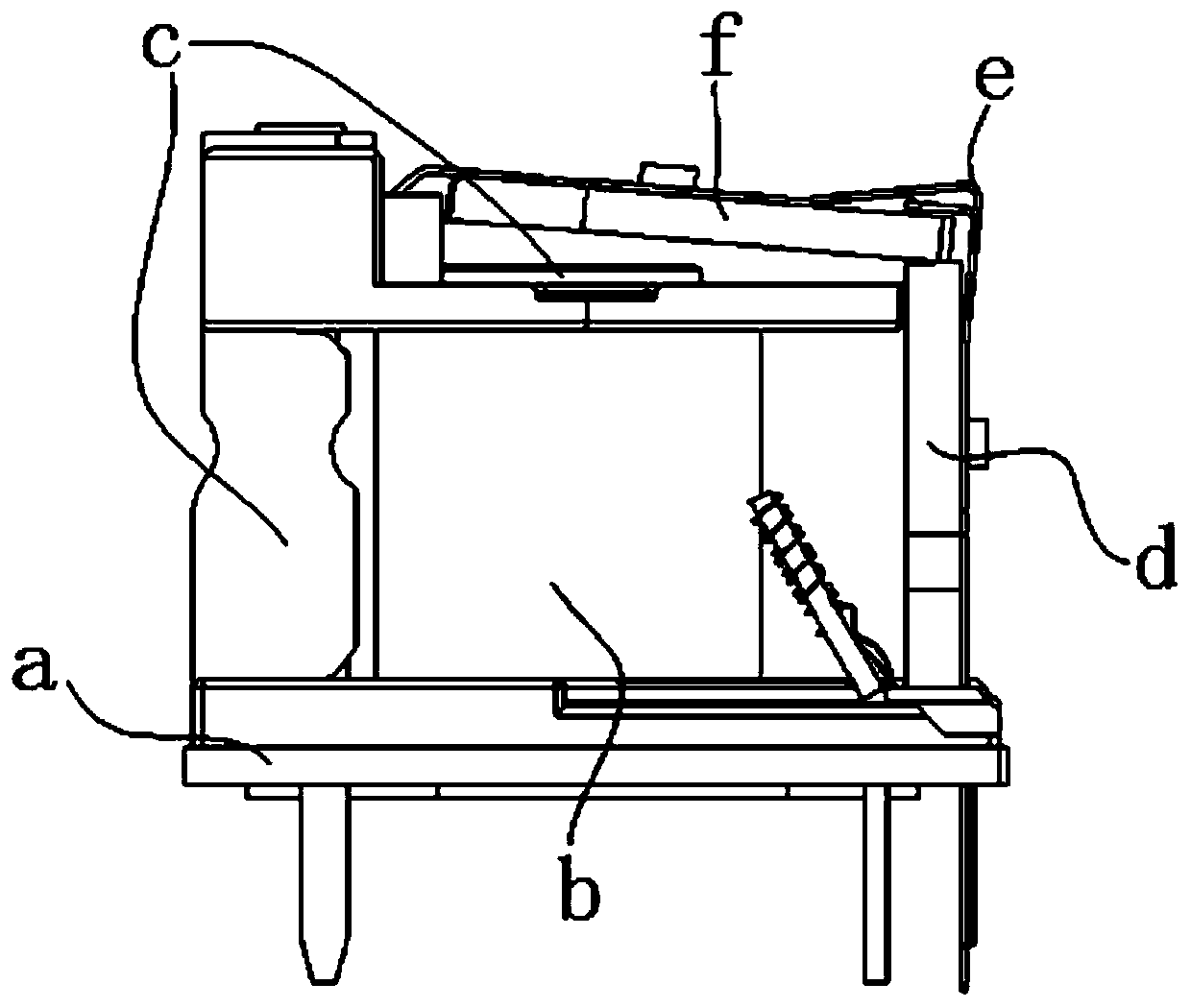
technical field [0001] The invention relates to a relay, in particular to a flip-chip, "sugar cube" small relay. Background technique [0002] The "sugar cube" type relay has the characteristics of simple structure, compact structure, small size and low power, and has been widely used in the power control of household appliances. [0003] A typical "sugar cube" type relay such as figure 1 As shown, it mainly consists of coil frame a, coil b assembled on coil frame a, iron core assembled in coil frame a, yoke iron d assembled on coil frame a, static spring assembled on coil frame a The component c, the moving spring component e assembled on the coil frame a, the armature f assembled on the yoke d through the moving spring component e, etc. In this relay structure, the moving spring assembly (mainly referring to the moving reed) extends to the top of the coil frame through the yoke and the armature, which plays the basic function of cooperating with the static spring assembl...

Claims


Application Information

Patent Timeline
IPC IPC(8): H01H50/44H01H50/64
CPCH01H50/44H01H50/64
Inventor 吕江徐勇
Owner SICHUAN HONGFA ELECTROACOUSTIC
Learn More